Optical transport architecture
O²AT Type 1 and Type 2
Type 1 uses duplex optical Ethernet with receiver credits. Type 2 adds a dedicated optical timing path, either from the DAC back to the source or from a master reference forward to the DAC.
Why use 1G optical Ethernet for audio?
TOSLINK in consumer equipment typically carries S/P-DIF over plastic optical fibre. Many devices limit it to 96 or 192 kHz stereo PCM, with DSD64 via DoP available on some pairs. Those are equipment limits, distinct from the signalling rates of individual optical modules. S/P-DIF encodes timing with the data using biphase mark coding. The receiver recovers that timing to decode the signal. The DAC’s PLL, buffering and clock design determine how much recovered timing variation can reach conversion.
USB Audio over copper can share supply and ground conductors. External I²S over LVDS uses differential pairs, often on an HDMI-shaped connector. Its pinout, permitted cable length and timing margin depend on the implementation. Fibre breaks the conductive signal path between its endpoints. A coaxial clock lead, shield, power earth or another copper connection can still join the chassis.
The v0.2 draft specifies qualified duplex 1000BASE-SX for the baseline and permits explicitly qualified 1000BASE-LX single-mode links. The 1.25 GBd serial stream uses 8b/10b coding and provides 1.000 Gb/s of MAC service in each direction. Module-rated examples include up to 550 m on qualified 50 µm multimode fibre for SX, including suitable OM3 or OM4 installations, and 10 km over compatible single-mode fibre such as OS2 for LX/LH. Use the actual optical budget and module ratings for each hop. Cisco optical specifications.
On 1G, stereo PCM32 at 1,536 kHz carries 98.304 Mb/s of audio, and conventional stereo DSD2048 carries 180.6336 Mb/s. Admission must also account for framing, link overhead and traffic margins. The draft also includes stereo PCM32 at 2,822.4 and 3,072 kHz and a separately identified 48 kHz-derived DSD2048 rate. Calculate occupied Ethernet capacity.
Starting at 1G lowers the required SerDes rate and gives the receiver designer a choice of low-power optics. The Coherent FTLF8519P3xyL family, for example, specifies module dissipation below 500 mW. Cisco rates its 10GBASE-SR SFP-10G-SR-X at 1 W maximum. 10G SFP+ remains an optional route for higher channel counts. Module dissipation, regulator noise and coupling into the DAC must be assessed on the assembled design. Coherent module datasheet · Cisco 10G module power ratings.
O²AT puts a fixed 12-byte header and uncompressed PCM or packed native DSD in Layer 2 Ethernet frames. 0x88B5 is a local experimental EtherType for controlled testing. A hardware bridge can process the stream without IP, UDP or TCP. Host implementations still incur operating-system and scheduling costs when they use kernel interfaces such as raw sockets. v0.2 draft, §§5 and 7.
What the optical connection could look like
This hardware concept shows a transport and DAC connected through duplex LC fibre, alongside a separate clock generator. The complete original also illustrates the commodity SFP module and fibre lead. The illustrated chassis are a proposed arrangement.
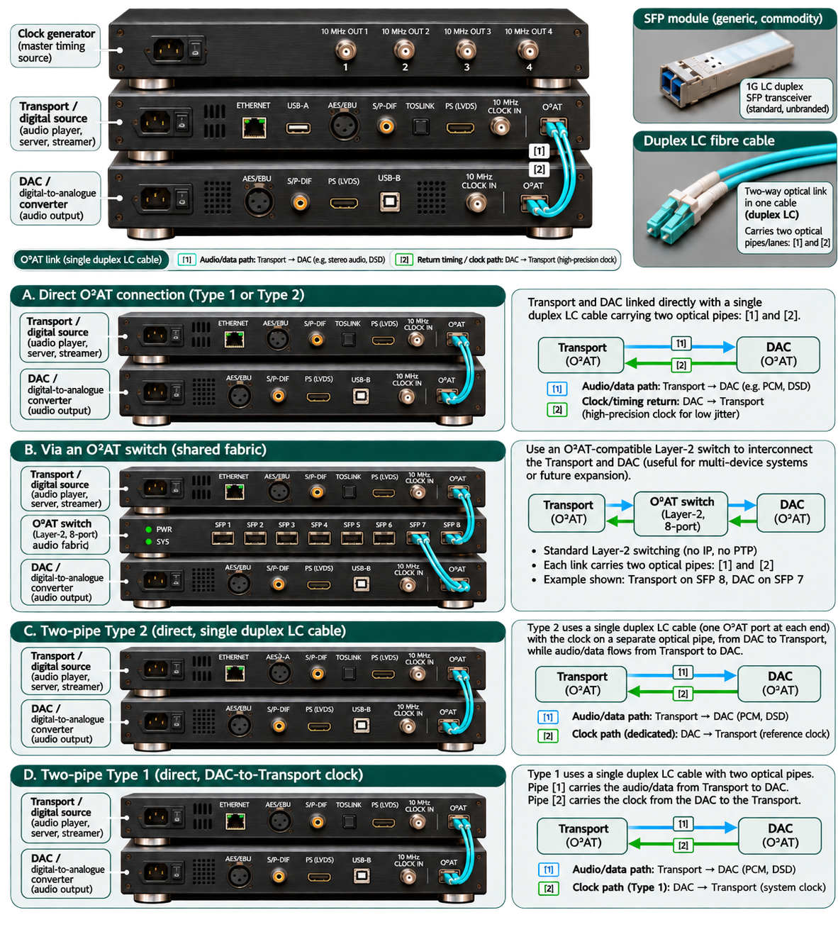
View the complete early concept image. Its Type 1 clock-return labels are superseded by the current diagrams.
Interactive architecture view
Trace the optical paths
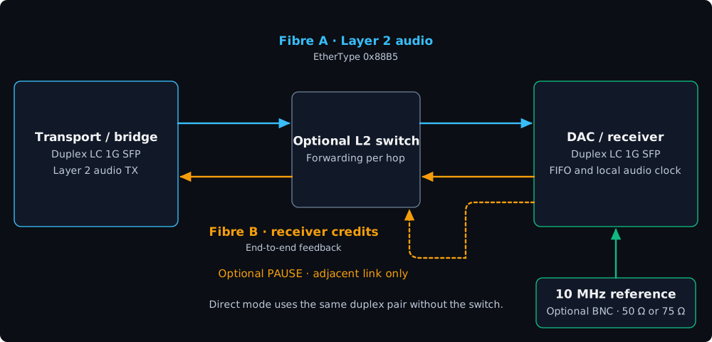
Choose a link arrangement and a stereo format. The drawing shows which direction each signal travels; the calculated load applies to the audio link only.
Select a format to calculate its occupied 1G MAC capacity.
Baseline arrangement, based on v0.2
Type 1 with a local DAC clock
Audio travels from the transport to the DAC. Cumulative receiver credits return over the other fibre. The DAC's local oscillator sets conversion timing.
The figures describe the proposed electrical and optical arrangements. They are not measurements of a working O²AT endpoint. Capacity assumes two channels, a 32-bit PCM transport container, one VLAN tag and a 125 µs packet target. Change the assumptions in the bandwidth calculator.
Compare the optical paths
Type 1 retains a return path for receiver credits. The proposed reference profiles assign a separate role to clock transfer, with different physical and control requirements.
Type 1 baseline; Type 2A and Type 2B proposed
Type 1 and Type 2 signal roles
Cyan carries audio towards the DAC. Amber returns receiver credits. Green identifies a candidate or separate optical reference. Type 2A still needs a defined runtime control path; Type 2B needs a second optical port.
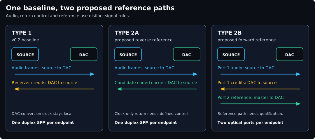
Read the diagram description
- Type 1 uses one duplex 1G SFP at each endpoint: audio forward, cumulative receiver credits back. The DAC conversion clock remains local.
- Proposed Type 2A uses one duplex SFP: audio forward, candidate coded reference back. A clock-only return cannot also carry the baseline credits and status without another defined mechanism.
- Proposed Type 2B uses port 1 for audio and credits and another optical port for a forward timing reference. The waveform and receiver require qualification.
Baseline tier
Type 1 · Duplex audio and receiver credits
One 1G duplex LC SFP at each endpoint supports a direct link or a qualified Layer 2 switched path. Fibre A carries the audio frames towards the DAC. Fibre B returns cumulative receiver credits and status. The DAC uses its local audio clock to drain the FIFO. A matched 10 MHz external reference can discipline that clock. The link’s own clock recovery serves Ethernet reception.
Baseline arrangement · based on v0.2
Type 1 signal paths
A switch forwards audio and receiver-credit frames. Optional PAUSE terminates at the neighbouring MAC. The coaxial 10 MHz reference is separate.
Read the diagram description
- Forward audio travels from the source through an optional managed Layer 2 switch to the DAC.
- Receiver-credit frames travel in the reverse direction. A PAUSE frame acts only on its adjacent Ethernet link.
- The local DAC oscillator sets conversion timing. An optional matched BNC reference can discipline it.
IEEE 802.3x PAUSE can protect an adjacent link against temporary congestion. A switch does not forward the DAC’s PAUSE as an audio-rate command to the source. Receiver credits carry end-to-end pacing. Multi-room use additionally needs per-hop admission, suitable forwarding and explicit synchronisation if rooms must play to the same sample epoch. Cisco MAC flow-control guidance.
A 10 MHz source such as the MUTEC REF10 NANO provides a frequency reference. Match the BNC cable, input impedance and voltage to the receiver’s specification. Frequency discipline and sample-phase alignment are distinct engineering requirements. MUTEC BNC output specification.
Reference tier · proposed extension
Type 2A · Single-SFP reverse clocking
A direct duplex fibre pair connects the source and DAC. Fibre A carries forward Layer 2 audio. In clock-only operation, fibre B carries a repeating 8b/10b symbol pattern generated at a rate tied to the DAC’s audio reference. A candidate pattern uses a K28.5 comma with a following data symbol such as D21.5. Implementation must specify the sequence, running disparity and transition density.
Proposed profile · point-to-point
Type 2A reverse reference path
Audio flows towards the DAC. The DAC sends a coded optical carrier back towards the source. The source recovers its frequency and derives audio pacing.
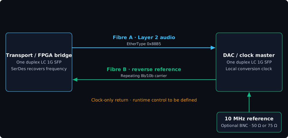
Read the diagram description
- One duplex LC SFP at each endpoint carries audio forward and a candidate repeating optical carrier in reverse.
- The DAC’s local oscillator, optionally disciplined by a 10 MHz reference, sets the carrier relationship and conversion timing.
- The source recovers the carrier with its SerDes. A clock-only reverse path needs a separately specified mechanism for runtime control and fault signalling.
At 1.25 GBd, a 10-bit code group corresponds to a 125 MHz rate. The source must qualify the recovered clock and derive the required audio-family rate. The 10 MHz reference, recovered PHY clock and DAC sample clock have defined relationships and separate functions. Even with common frequency, elastic storage, packet admission and safe clock-loss handling still matter. Repeating symbols remove varying packet contents from the carrier. Residual jitter from the reference, transmitter, optical receiver and CDR remains a measurement item.
A clock-only return cannot simultaneously carry v0.2 receiver credits or status. Before Type 2A can be implemented as an interoperable profile, it needs a defined control path or a specified change between negotiation and clock-only operation, with explicit rules for prefill, stop, loss of lock and restart. Standard SFP modules are candidates. The module, host SerDes and non-standard clock-only mode require qualification together.
Reference tier · proposed extension
Type 2B · Dual-SFP forward clocking
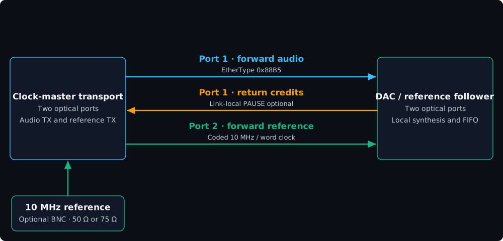
Each endpoint has two optical ports. Port 1 carries the baseline duplex audio and control traffic, including end-to-end receiver credits and any optional link-local PAUSE. Port 2 carries a separate forward reference from the clock-master transport or a qualified master-clock optical transmitter to the DAC. A duplex module has one transmitter in each endpoint, so the second forward signal requires a second physical optical path.
Proposed profile · separate optical reference
Type 2B forward reference path
Port 1 carries forward audio and return control. Port 2 carries a forward reference independently of the Ethernet traffic.
Read the diagram description
- The clock-master transport sends audio to the DAC on port 1. The DAC returns credits on the same duplex link.
- A separate optical transmitter sends a coded or otherwise qualified reference to the DAC’s clock receiver on port 2.
- An optional matched 10 MHz BNC input disciplines the clock master. The DAC’s local synthesis and converter use the recovered reference relationship.
The reference path may represent 10 MHz or a specified word-clock family. Ordinary Ethernet SFPs must not be assumed to accept a raw low-frequency square wave. Define line coding or qualify a purpose-built transmitter and receiver, then measure lock acquisition, loss, jitter transfer and frequency accuracy. The reference path is point-to-point. Any switched data path remains subject to the Type 1 admission rules.
Interface comparison
| Characteristic | TOSLINK | USB Audio (UAC 2.0) | I²S LVDS (HDMI connector) | O²AT Type 1 | O²AT Type 2A | O²AT Type 2B |
|---|---|---|---|---|---|---|
| Physical medium and connector | Plastic optical fibre and keyed EIAJ/TOSLINK connector. | Copper USB. VBUS and ground may be present. | Copper differential pairs with vendor-specific pinouts. | One duplex LC 1G SFP per endpoint. | One duplex LC 1G SFP per endpoint. Reverse fibre carries the candidate clock carrier. | Two optical ports per endpoint. Duplex audio/control link plus dedicated forward reference. |
| Galvanic isolation | Across the optical link. | Requires a suitable isolation design. | Requires a suitable isolation design. | Across the optical link. Optional BNC reference can join grounds. | Across both fibres. Optional BNC reference can join grounds. | Across both optical links. Check other cables and chassis bonds. |
| Audio formats and rates | Common stereo PCM examples up to 24-bit / 192 kHz. DSD64 via DoP on compatible equipment. | Host and endpoint dependent. Existing examples accept 705.6 and 768 kHz PCM. | Endpoint dependent. Published examples reach 1,536 kHz PCM. Native DSD1024 was tested on selected equipment. | Proposed PCM32 to 2,822.4 or 3,072 kHz and native DSD2048, subject to admission. | Proposed PCM32 to 2,822.4 or 3,072 kHz and native DSD2048, subject to admission. | Proposed PCM32 to 2,822.4 or 3,072 kHz and native DSD2048, subject to admission. |
| Ethernet switch compatibility | No. | No. USB hubs are a different topology. | No. | Direct or qualified Layer 2 switching. | Point-to-point. A switch does not preserve the reverse PHY carrier. | Direct reference profile. Only the data path could be switched after qualification. |
| Flow control and pacing | Source sends continuously. No return channel. | Asynchronous endpoints can report audio-rate feedback to the host. | Separate clock and data signals. No common credit scheme. | End-to-end receiver credits. Optional PAUSE acts on each adjacent link. | Source follows recovered frequency. Runtime control and fault signalling still need a defined path. | Receiver credits on the data link. Optional adjacent-link PAUSE. |
| Conversion clock | Receiver recovers S/P-DIF framing and timing. DAC clock handling varies. | An asynchronous DAC can use its local audio clock. | Source supplies bit and word clocks. Receiver conversion design varies. | DAC local clock, optionally disciplined by a 10 MHz reference. | DAC owns conversion and supplies the source with a timing reference. | DAC uses a local clock disciplined by the recovered forward reference. |
| Maximum cable reach | Transmitter, receiver and cable specification determine reach. | Depends on USB speed, cable and any active extension. | Depends on driver, receiver, cable and clock rate. | Qualified link budget. Examples: SX up to 550 m on 50 µm fibre, LX/LH up to 10 km on single-mode fibre. | Audio link as above. Reverse-carrier reach needs separate qualification. | Audio link as above. Qualify the reference link independently. |
Swipe or scroll horizontally to compare all six interfaces.
For other optical designs and network media transports, see existing SFP audio links and audio over IP and network-audio protocols.
Open specification and FPGA validation plan
The project intends to publish an open Layer 2 specification and reference designs without O²AT royalties. The v0.2 draft proposes MIT licensing for software and RTL and CERN-OHL-P v2 for hardware. Third-party FPGA IP and tools retain their own terms. v0.2 draft, §§4 and 7.
The Sipeed Tang Mega 138K Pro Dock is a candidate platform. Its Gowin FPGA and two SFP+ cages make it possible to investigate a qualified 1.25 GBd implementation. A RISC-V soft core or supported integrated processor can handle configuration and telemetry. The timing-critical PCS, comma alignment, MAC, packing and FIFO belong in hardware. No O²AT hardware validation results are published for this platform.
Validation should capture recovered clock quality, K28.5 alignment, bit errors, 10 MHz discipline, FIFO occupancy under load, measured latency and restart behaviour. Type 2 also needs a qualified waveform, control behaviour and reference-loss tests before conformance can be claimed. O²AT validation plan · Sipeed board and toolchain documentation.