
OPEN AUDIO ARCHITECTURE SPECIFICATION • VERSION 0.2
Open Optical Audio Transport (O2AT)
An open Layer-2 optical successor to TOSLINK, centred on low-power 1G SFP
This table is wider than the reading column. Scroll horizontally to read all columns.
| Specification field | Details |
|---|---|
| Protocol identifier | O2AT in prose; o2at in code, identifiers and schemas |
| Version and status | v0.2 engineering draft for manufacturer and community review; proposed wire-version nibble 0x2 |
| Author | Tunji Durodola (LinuxProphet) Principal Systems Architect, pocketOne OÜ |
| Revision date | 19 November 2026 |
| Mandatory physical baseline | 1000BASE-X at 1.25 GBd; 1000BASE-SX optics, 850 nm, duplex LC glass fibre; 1.000 Gb/s MAC service |
| Transport envelope | PCM in 32-bit containers through 2,822.4 and 3,072 kHz; native packed DSD through DSD2048; 2–32 channels subject to admission |
| Ethernet framing | Raw IEEE 802.3 Layer 2; local experimental EtherType 0x88B5; fixed 12-byte o2at header; standard 1,500-byte MTU |
| Clock architecture | Receiver-owned conversion clock with elastic buffering and source feedback; external 10 MHz input mandatory for the reference tier |
| Optional expansion | 10GBASE-R for aggregation or channel counts exceeding the admitted 1G budget; not required for the stereo replacement profile |
| Open implementation policy | Proposed MIT software/RTL and CERN-OHL-P v2 hardware releases; openly published specification and interoperable test vectors |
Revision focus
Version 0.2 makes 1G SFP the default endpoint design, doubles the earlier maximum format rates and replaces unsupported claims about optical modules with explicit budgets. It retains standard Ethernet framing, adds a precise receiver-paced control model and separates transport capability from existing DAC, USB and I²S limits. This document is a proposal, not a ratified standard or a claim that compliant products already exist.
1. Executive Summary & Problem Statement
O2AT proposes a durable replacement for the consumer optical audio socket: inexpensive duplex glass fibre, a standard pluggable optical module and an openly specified audio protocol. The primary connection is a direct source-to-DAC link that requires neither an IP address nor a network administrator. The core standard is 1G SFP; the optional 10G fabric is not part of the minimum consumer replacement requirement. Its purpose is to preserve TOSLINK’s most valuable property, a non-conductive signal path, while removing the installed base’s restrictive format envelope and dependence on an embedded audio clock.
The engineering centre of gravity in v0.2 is 1G SFP. A 1.25 GBd 1000BASE-X link offers a 1.000 Gb/s MAC service after line coding. With the framing defined here, stereo PCM32 at 3,072 kHz occupies 203.981 Mb/s including a VLAN tag, Ethernet framing, preamble and interpacket gap. Stereo native DSD2048 in the explicit 48 kHz-derived extension occupies the same rate. Eight channels occupy 815.923 Mb/s. These are calculated transport budgets, not announcements of commercial playback support.
The audio samples cross an asynchronous FIFO before conversion. The DAC-side clock sets the consumption rate; packet arrival determines only when data become available. Every source obeys receiver credits; coherent sample-clock discipline may additionally control its long-term production rate. This removes packet-arrival timing from the intended conversion-clock path. It does not remove the receiver’s own clock phase noise, supply coupling, metastability risks or the consequences of a FIFO underflow.
A reference-tier receiver shall provide a specified 10 MHz reference input, an independently engineered audio clock generator, lock monitoring and controlled holdover. Entry-level O2AT remains useful with an internal oscillator and receiver feedback. Requiring an external reference for every consumer installation would obstruct the central objective of replacing TOSLINK with a simple, dependable optical connection.
1.1 What changes in v0.2
- The baseline is 1000BASE-X and 1000BASE-SX, with 10G retained as an optional fabric and high-channel-count profile. A mechanical SFP+ cage may host a qualified 1G module when its host electronics support that rate.
- The format namespace extends PCM to 2,822.4/3,072 kHz and raw DSD to 90.3168 MHz per channel, plus an explicitly labelled 98.304 MHz extension. Exact integer rates replace the overflowing one-byte multiplier field in the attached draft.
- The audio header is consistently 12 bytes. PCM is big-endian, left-aligned in 32-bit containers. DSD uses chronological, most-significant-bit-first blocks. Wire version 0x2 intentionally supersedes the incompatible draft header.
- Ethernet PAUSE is treated as link-local congestion control. End-to-end receiver credit and upstream clock feedback address sustained rate mismatch. Generic switches do not confer a deterministic latency guarantee.
- Manufacturer comparisons distinguish documented behaviour from proprietary implementation details. MSB Pro ISL, HiFi Rose optical USB and standard Ethernet optics share components without sharing a wire protocol.
1.2 Scope, terminology and conformance
“Shall” identifies a proposed v0.2 conformance requirement; “should” identifies a recommendation; “may” identifies an option. The normalised machine-readable prefix is o2at. A device shall advertise only formats it can accept, buffer and deliver at its physical audio output. A link can carry a format that the attached conversion engine cannot reproduce, so negotiation shall reject unsupported modes before audio starts.
O2AT is a Layer-2 protocol within a single bridged Ethernet domain. Switches can bridge its Ethernet frames; ordinary IP routers do not route them. The prototype EtherType is experimental and shared with other experiments, so v0.2 is appropriate for controlled evaluation networks pending a production identifier and a completed interoperability programme. The proposal neither claims universal patent clearance nor grants rights over third-party standards or vendor IP cores.
2. History of TOSLINK and Legacy Optical Audio Interfaces
TOSLINK was developed by Toshiba during the early compact-disc era. Its introduction is commonly dated to 1983; a contemporaneous Toshiba archival source for that date was not located for this revision. The historical lineage includes EIAJ CP-1201 and consumer digital-audio interface work associated with IEC 60958. JIS F05 describes the familiar optical connector family. These are related layers of an interface ecosystem, not interchangeable names for a single physical bandwidth limit.1
The original design solved a practical problem well: it connected domestic digital equipment without an electrical conductor between the two signal ports. Its limitations arise from the combination of inexpensive optical components, the installed digital receiver population, embedded-clock framing and a narrow common capability set. The case for replacement is stronger when it acknowledges that properly implemented TOSLINK already provides galvanic isolation and can deliver error-free audio within its supported envelope.
2.1 Physical limits, line coding and the installed base
Typical consumer assemblies use a red LED near 650 nm and approximately 1 mm plastic optical fibre, commonly PMMA. The large core and high numerical aperture make coupling inexpensive, but step-index propagation admits many paths with different transit times. Modal dispersion, attenuation, bends, connector contamination and finite transmitter/receiver bandwidth can close the eye and shift threshold crossings. The degree depends on the complete link; a universal failure distance of three or five metres is not defensible.2
Toshiba’s TOTX1950A(F) illustrates why component-specific evidence matters: it specifies a 650 nm LED, JIS F05 coupling and a 10 Mbit/s NRZ operating limit. That is the rating of one transmitter under stated conditions, not an immutable ceiling imposed by every F05 connector. NRZ data-rate ratings, pulse-width distortion and the minimum pulse width required by a BMC stream must be reconciled before a valid audio-rate limit can be inferred.3
A conventional stereo IEC 60958 frame contains two 32-bit subframes. Its logical bit-period rate is 64 × Fs, while Bi-Phase Mark Coding resolves each period into half-bit intervals at 128 × Fs. At 192 kHz, those figures are 12.288 Mbit/s and a 24.576 MHz half-bit grid. BMC guarantees useful transitions but embeds timing in the same waveform as the data. Pattern-dependent edge displacement can therefore become recovered-clock jitter through a receiver’s clock-recovery transfer function.
That coupling is not proof that all optical edge jitter reaches the analogue output. A suitable PLL, asynchronous sample-rate conversion or a locally clocked elastic architecture can attenuate it, each with different requirements and consequences. Error-free bits and conversion-clock quality are separate questions. O2AT’s proposed improvement is to make the separation explicit in the transport architecture, rather than relying on undocumented receiver behaviour.
Conventional consumer TOSLINK commonly tops out at stereo 24-bit/96 or 192 kHz, depending on both endpoints and the cable. This is an installed-base interoperability ceiling. It is not a universal theorem about plastic fibre, F05 or the whole IEC 60958 family: IEC 60958-5 adds consumer enhancements for multichannel and higher-resolution applications. O2AT deliberately adopts a new common transport profile rather than attempting to infer support for those extensions from an existing optical socket.4
DoP is lossless packaging of DSD bits, not lossy conversion to PCM. In the standard arrangement, 16 DSD bits occupy a 24-bit PCM-shaped container with an eight-bit marker. The disadvantage is transport overhead and sensitivity to inappropriate PCM processing. Native o2at DSD avoids that wrapper and carries the one-bit sequence directly; it does not improve the numerical fidelity of an already bit-perfect DoP transfer.5
2.2 Comparative limitations of legacy interfaces
This table is wider than the reading column. Scroll horizontally to read all columns.
| Interface | Medium and isolation | Typical installed capability | Conversion timing | Interoperability issue | O2AT implication |
|---|---|---|---|---|---|
| TOSLINK | F05 optical; non-conductive fibre path | Stereo PCM, commonly 24-bit/96 or 192 kHz | Embedded BMC clock; receiver design governs rejection | One-way link; no general capability negotiation | Retain simple optical use; replace restricted common envelope |
| Coaxial S/P-DIF / AES3 | Copper; isolation depends on transformers, shields and implementation | Conventional stereo PCM through 192 kHz; extensions vary | Embedded clock with receiver PLL | Electrical and connector variants; no universal high-rate extension | Standardise optical endpoint behaviour and return control |
| Asynchronous USB audio | Usually copper; galvanic isolation needs additional design | Format and rate depend on endpoint, driver and firmware | Sink feedback controls average audio delivery; USB signalling clock is separate | Class compatibility does not guarantee native DSD or extreme rates | Use as optional ingress, not the definition of the optical link |
| I²S over HDMI LVDS | Metallic cable and connector; not HDMI audio signalling | Vendor-specific PCM/DSD rates and lane assignments | Source or sink clock arrangement is vendor-specific | No common external pinout for clocks, DSD flags and channel polarity | Replace exposed timing/pinout negotiation with a defined packet format |
| O2AT v0.2 proposal | Duplex LC glass fibre; no conductor along the signal link | PCM32 through 3,072 kHz; DSD2048; channel count admitted by budget | Receiver-owned clock, FIFO and source-rate control | Requires new endpoints and conformance testing | Mandatory 1G optical baseline; optional higher-density 10G fabric |
Capability entries describe common implementations or the proposed transport envelope. They do not certify every device bearing a connector. NXP defines I²S as an inter-IC bus, not a universal HDMI cable pin assignment.6
3. Landscape Analysis: AoIP and Proprietary Optical Links
3.1 Professional transports solve a broader problem
AES10 MADI established a useful precedent for dedicated serial multichannel audio. Its channel structure and professional installation model differ from a modern consumer replacement socket. AES67, RAVENNA and Dante address networked audio systems with multiple endpoints, stream descriptions, timing distribution and managed routing. O2AT should not dismiss those capabilities as inherently noisy or incapable of low latency; it deliberately chooses a smaller application scope.7
AES67 specifies interoperability requirements for audio over IP, including synchronisation and media transport. RAVENNA is a broader networking technology and ecosystem, while Dante has proprietary transport and management elements with AES67 interoperability available on supported products. It would be incorrect to assert that every AES67 endpoint mandates SIP, RTSP, mDNS and all other discovery mechanisms simultaneously. Their presence and roles depend on the implementation and system profile.
AVB and Milan already demonstrate standards-based Layer-2 audio with synchronisation, stream reservation and constrained network behaviour. Milan builds endpoint interoperability on the IEEE AVB family, including 802.1AS and IEEE 1722/1722.1. O2AT does not invent deterministic Ethernet. Its proposed distinction is a simpler optical consumer profile, native DSD packing, an explicit high-rate envelope and an optional external reference architecture without mandatory network time synchronisation.8
3.2 HiFi Rose: optical USB and optical Ethernet are different
HiFi Rose validates the practical use of pluggable optical interfaces in hi-fi equipment, but its ports must be distinguished. The documented RS130-to-RD160 connection uses USB 3.0 FIBER at the source and SFP AUDIO IN at the DAC, with RD160-DAC selected in the source’s output settings. This is a manufacturer-specific optical USB connection, not an open audio protocol carried by an Ethernet MAC. The RS130’s optical Ethernet networking function is a separate interface.9
Public manuals do not disclose enough framing detail to reverse-engineer that USB optical transport. Nor should every Rose link be described as 850 nm duplex-LC 1G SFP: the separate RSA720 optical USB hub manual specifies paired BiDi SFP+ optics. Its restrictions also preclude treating it as a universal bridge for every USB 2.0 DAC. O2AT therefore specifies its own optical baseline and Ethernet framing instead of inferring compatibility from a similar cage.
3.3 MSB Pro ISL and Aurender N50: the relevant lesson
Aurender documents an optional MSB Pro ISL output for the N50, with PCM through 768 kHz and native DSD512 among the module’s advertised capabilities. A native Pro ISL output permits a compatible MSB DAC connection without placing an external Pro USB adapter in that particular signal chain. This is evidence of cross-manufacturer implementation, but the public documentation does not establish the contractual details of FPGA-core licensing or universal compatibility with other modular Aurender products.10
MSB explicitly identifies Pro ISL as non-Ethernet. Its fibre guidance specifies matched single-mode optics and duplex LC fibre, including a 1310 nm module family, rather than establishing 850 nm 1000BASE-SX as the universal MSB implementation. The guide also distinguishes Pro ISL from other MSB optical links. An Ethernet switch is therefore not a compatible intermediary, and an arbitrary module should not be inserted into an MSB port merely because it fits the cage.11
MSB describes a return copy of the DAC master clock to the source, together with error handling. The important architectural lesson is receiver clock authority across an isolated connection. Public evidence does not disclose the exact serial line rate, frame format, 8b/10b use or internal FIFO topology. Those details must remain unspecified here. The Pro USB adapter is a USB-to-Pro-ISL path, not an obligatory component of every MSB digital input configuration.12
O2AT adopts the general benefits of optical isolation, buffered reception and explicit timing control, while retaining an ordinary Ethernet MAC and a published protocol. A raw proprietary FPGA serial bus and standard Layer-2 Ethernet can both use SFP hardware. That shared hardware does not make their frames or clocks interoperable.
3.4 Comparative landscape
This table is wider than the reading column. Scroll horizontally to read all columns.
| System | Transport | Clocking model | Strength | Limit relative to this proposal |
|---|---|---|---|---|
| MADI / AES10 | Dedicated serial multichannel interface | Embedded transport timing and system clock arrangements | Established professional multichannel interconnect | Different rate/channel framing; not a commodity switched consumer profile |
| RAVENNA / AES67 | IP, UDP and RTP media transport | PTP-based network synchronisation in the AES67 profile | Interoperability and distributed professional systems | Broader system configuration and clock-servo responsibilities |
| Dante | Proprietary network transport; AES67 modes on supported devices | Network-synchronised audio; implementation-dependent modes | Mature routing and product ecosystem | Vendor technology and format capabilities vary by implementation |
| AVB / Milan | IEEE Layer-2 audio and network services | 802.1AS plus defined media clocking | Reservation, timing and endpoint interoperability | Requires the appropriate AVB network and endpoint profile |
| HiFi Rose optical USB | Manufacturer-specific USB optical connection | USB/audio endpoint behaviour | Consumer use of pluggable optical interfaces | Not an open Ethernet audio protocol; optical kits differ |
| MSB Pro ISL / N50 module | Proprietary point-to-point optical link | DAC master-clock return documented by MSB | Isolated receiver-led digital connection | Closed wire format; no ordinary Ethernet switch compatibility |
| O2AT v0.2 | Open raw Layer-2 Ethernet proposal | Local or 10 MHz-disciplined DAC clock; receiver pacing | 1G SFP default; explicit PCM/DSD packing and capabilities | New implementation, validation and governance required |
No row implies measured sonic superiority. Packet overhead is only one implementation cost; clock architecture, isolation, analogue design and verifiable interoperability determine the practical result.
4. O2AT Design Objectives & Architectural Principles
The replacement must be understandable to a listener and precise enough for two independent engineering teams to implement. A direct optical connection should discover its peer, agree a supported format, prefill a bounded buffer and start safely. It should not require the listener to choose clock-recovery constants, FPGA pins or a network addressing scheme.
4.1 Three implementable profiles
This table is wider than the reading column. Scroll horizontally to read all columns.
| Profile | Required behaviour | Permitted expansion |
|---|---|---|
| o2at-basic | 1G optical Ethernet, direct-link discovery, stereo PCM32 containers at 44.1 and 48 kHz with 16/24/32 valid bits, capability negotiation, receiver credits, safe mute and diagnostics | Additional PCM rates, native DSD and more channels when explicitly advertised |
| o2at-reference | All basic functions plus a documented 50 Ω 10 MHz input, selectable internal/external clocking, lock/holdover reporting and measured clock performance | High-rate PCM/DSD and multiple channels as validated; external reference is not required to obtain link-up |
| o2at-fabric | Standard Layer-2 bridging and admission across documented switch configurations; endpoint profiles remain explicit | Optional 10GBASE-R uplinks and endpoints for aggregation or rates beyond 1G admission |
A high-rate capability claim is additional to the profile name. A manufacturer may advertise “PCM32/3072, DSD2048/44.1, 8 channels at 1G” only after validating those combinations. The high-rate envelope does not force every affordable TOSLINK replacement to implement a multi-megahertz conversion engine.
4.2 Isolation, openness and a stable channel model
The fibre assembly shall contain no conductive path between the two O2AT ports. This isolates the signal link galvanically. It does not guarantee isolation of the entire installation when protective earth, USB, analogue interconnects or shared coaxial reference-clock distribution also connect chassis. Safety-earth arrangements must remain governed by the equipment design; the protocol cannot cancel an external conductive path.
PCM and DSD shall be transported without implicit volume control, sample-rate conversion, channel reordering or DoP insertion. Any processing belongs to an explicitly selected endpoint function outside the transparent transport mode. Two-channel ordering is left then right. Additional channels use a negotiated map with defined logical channel identifiers, replacing the undocumented clock/data/flag assignments associated with I²S over HDMI.
Reference RTL, packet encoders, dissectors, schematics and conformance vectors should be published under clear open licences. The proposed release policy is MIT for software/RTL and CERN-OHL-P v2 for hardware, with a separately stated open document licence for the specification. Third-party PHY IP and vendor tools retain their own licence conditions. No existing open reference implementation is claimed by this paper.
4.3 Replacing TOSLINK variants and allowing future ADAT
The target connection family includes rectangular F05 TOSLINK and 3.5 mm mini-TOSLINK. Those mechanical variants can carry the same optical consumer signal; changing their plug shape does not define a new audio coding system. O2AT replaces that connection with a negotiated duplex SFP link. Existing optical sources require an active bridge with the appropriate receiver and framing decoder, not a passive F05-to-LC adaptor.13
A complete migration must also distinguish programme types. Stereo PCM samples can map into the present PCM32 mode, and a recognised DoP stream can be unpacked to native DSD without changing its DSD bits. IEC 61937 encoded bursts and IEC 60958 channel-status, user and validity information require a separately defined legacy-carriage profile if transparent preservation is intended. Version 0.2 does not label those non-PCM bursts as ordinary PCM or promise their automatic decoding.14
This table is wider than the reading column. Scroll horizontally to read all columns.
| Legacy use | O2AT path | Scope or additional requirement |
|---|---|---|
| Rectangular TOSLINK or mini-TOSLINK carrying PCM | Native SFP source/receiver, or active legacy bridge to negotiated PCM32 | v0.2 audio transport; bridge must specify clock authority and treatment of legacy status bits |
| DoP on a supported optical PCM carrier | Detect and unpack unchanged DSD bits into DSD32 | Bridge capability must be advertised; reject ambiguous or damaged marker sequences |
| IEC 61937 encoded audio and full IEC 60958 metadata | Future explicit legacy-carriage profile | Preserve burst framing and metadata; keep separate from transparent PCM/DSD claims |
| ADAT Lightpipe, including S/MUX variants | Possible future ADAT bridge/profile using the existing multichannel PCM transport | Decode and map channels explicitly; define input-clock tracking or common-clock operation before claiming interoperability |
ADAT is a separate multichannel framing system that often uses TOSLINK-shaped optical ports. A documented example is eight 24-bit channels at 48 kHz per ADAT port, falling to four at 96 kHz and two at 192 kHz through S/MUX arrangements. Those channel/rate combinations do not challenge 1G capacity. They do require a defined bridge, channel map and live-clock relationship. ADAT is therefore a credible future profile, not a feature implied by an LC connector.15
For example, eight channels of 24-bit/48 kHz PCM occupy 12.288 Mb/s in o2at 32-bit containers. With six groups per 125 µs packet, the 192-byte payload occupies 15.744 Mb/s including a VLAN tag and all stated framing. Four channels at 96 kHz or two at 192 kHz have the same container and wire rates under this packetisation policy. This is a transport calculation, not a claim that v0.2 already implements ADAT framing or synchronisation.
5. Physical Layer & Wire Protocol Specification
5.1 Mandatory 1G optical baseline
The baseline shall implement an IEEE 802.3 Ethernet MAC with 1000BASE-X PCS/PMA at 1.25 GBd, full duplex. Its common optical profile is 1000BASE-SX at 850 nm using matched duplex-LC modules and OM3 or OM4 multimode glass fibre. Optional 1000BASE-LX single-mode links shall be identified explicitly and use qualified optics and fibre at both ends. A connector alone does not identify wavelength, launch power, receiver sensitivity or Ethernet compatibility.16
The source and receiver each contain a transmitter and a receiver. One fibre carries source-to-sink audio; the other carries discovery, control, credits and status in the opposite direction. Ethernet capacity is full duplex, so reverse control traffic does not consume the forward link’s serial bandwidth. MAC processing and buffers still require capacity for both directions.
A host shall implement module presence, transmit disable, loss-of-signal and fault handling, appropriate power sequencing and the required electrical interface. It should expose module identity and supported diagnostics. Only qualified module classes should be enabled. A 10G-only host cannot be presumed to operate a 1G SFP, and replacing an optic does not change the host PCS or SerDes rate. The baseline shall implement and enable 1000BASE-X auto-negotiation, advertising full duplex. Forced operation is an explicit paired-test option. Optional PAUSE capability shall be advertised and configured consistently; speed and duplex shall be reported.
The receiver reference design should begin with a low-power optical module, preferably a qualified part below 0.5 W, but this is an endpoint engineering target rather than a redefinition of an MSA power class. Coherent’s FTLF8519P3xyL provides a documented example below 500 mW. The complete budget must add the cage interface, FPGA transceiver, PCS/MAC, memories, regulators and clock circuitry.17
5.2 Revised SFP and SFP+ engineering assessment
This table is wider than the reading column. Scroll horizontally to read all columns.
| Parameter | 1G SFP baseline | 10G SFP+ option | Design conclusion |
|---|---|---|---|
| Serial rate and MAC capacity | 1.25 GBd; 8b/10b; 1.000 Gb/s MAC service | 10.3125 GBd; 64b/66b; 10.000 Gb/s MAC service | Neither MAC figure is net audio capacity. Include all packet overhead and admission margin. |
| Optical module power | Named example: Coherent FTLF8519P3xyL below 500 mW | Named example: Cisco 10GBASE-SR variants specify 1 W maximum | 1G is a sensible low-power starting point. Do not impose a universal 2× or 3× power ratio. |
| CDR / internal retiming | Many 1G modules rely on host clock recovery | An internal CDR is not mandatory for every SFP+ module | SFF-8472 identifies optional retimer/CDR presence. Qualify the actual module and host pair. |
| RF and supply coupling | Lower serial rate generally eases implementation | Higher rate can increase SerDes and power-integrity demands | Measure coupled noise. Baud rate is not a single EMI fundamental or evidence of audibility. |
| FPGA interface | Compliant 1.25 GBd SerDes or qualified external PHY | Compliant high-speed SerDes and SFI channel | Ordinary LVDS pins alone do not guarantee CDR, comma alignment or PCS compliance. |
| PCB material and layout | Controlled impedance, return paths and validated losses remain necessary | Short standard-FR4 channels can be feasible within the applicable loss budget | 10G does not universally mandate an exotic laminate; qualify the actual stack-up and route. |
| Role in O2AT | Mandatory endpoint baseline; stereo and admitted eight-channel extreme formats | Optional 16/32-channel extreme formats, aggregation and shorter serialisation | Choose 1G for the consumer socket. Preserve 10G where the payload or topology benefits. |
Evidence: module power examples, optional CDR indication and host-channel guidance.18
5.3 Ethernet envelope and identification
8b/10b constrains run lengths and bounds running disparity. It does not produce an exact 50% optical duty cycle in every symbol. Its purpose includes reliable serial recovery and AC-coupled channel behaviour; a laser is not physically unable to remain on or off for a long run. The 1G SerDes still performs clock recovery even when the pluggable module has no CDR.19
The packet path is audio packing, o2at header, Ethernet MAC, 1000BASE-X PCS/PMA and optical conversion. Standard destination and source MAC addresses remain present. There are no IP, UDP, RTP or TCP headers. The MAC supplies the normal Ethernet FCS, preamble, start delimiter and interpacket gap. The PCS supplies 8b/10b coding at 1G or 64b/66b at 10G. These are distinct layers, and the o2at encoder shall not add another private line-code layer.
Laboratory v0.2 frames use EtherType 0x88B5. This is a local experimental EtherType, not a permanent O2AT allocation. Its use shall remain inside the developing organisation’s controlled evaluation domain; a production release needs an appropriately assigned protocol identifier. The lowercase four-byte magic in every packet improves experimental demultiplexing but does not create ownership of the EtherType.20
The minimum interoperable Ethernet MTU is 1,500 bytes. Jumbo frames are not required. Audio payload is capped at 1,440 bytes in v0.2, leaving 48 bytes of unused MTU after the fixed header. Control payload may occupy up to 1,488 bytes. Packets shorter than the Ethernet minimum are padded by the MAC; padding is excluded from the o2at audio-group count and control-body length. Receivers shall validate the complete implied length before accepting data.
A single optional 802.1Q tag may use PCP 6 when the network administrator has mapped that priority appropriately. PCP is a scheduling request, not a reservation or latency guarantee. The default direct link is untagged. Do not send user audio to IEEE bridge-control multicast addresses such as 01:80:C2:00:00:2F. Discover with bounded broadcast traffic on an isolated evaluation link, then use unicast MAC addresses and explicit session admission.
A switch shall be qualified for forwarding the experimental EtherType, the selected VLAN, frame sizes, multicast or broadcast policy and required egress capacity. Network ACLs, port security, unknown-protocol filtering and energy-saving policies can affect operation. No EtherType value guarantees universal NIC driver exposure or switch forwarding. Raw-socket software must likewise be tested against the actual NIC and operating system.
5.4 Fixed 12-byte common header
Offsets below are relative to the beginning of the Ethernet payload, immediately after EtherType. All multi-byte integers are big-endian. Wire version 0x2 occupies the upper nibble of byte 4; it is not a standalone 0x02 byte. The format and channel configuration are immutable session context, established before audio. This header supersedes the inconsistent 18-byte layout in the attached v0.1 draft.
This table is wider than the reading column. Scroll horizontally to read all columns.
| Offset | Size | Field | v0.2 encoding and validation |
|---|---|---|---|
| 0 | 1 byte | magic[0] | 0x6f, ASCII lowercase o |
| 1 | 1 byte | magic[1] | 0x32, ASCII 2 |
| 2 | 1 byte | magic[2] | 0x61, ASCII lowercase a |
| 3 | 1 byte | magic[3] | 0x74, ASCII lowercase t |
| 4 | 1 byte | version_type | Bits 7:4 = 0x2. Bits 3:0: 0 = AUDIO; 1 = CONTROL; 2 = FINAL_AUDIO. Other types are reserved and discarded. |
| 5 | 1 byte | count | AUDIO: group count, 1–180 with 4 × channels × count ≤ 1,440. CONTROL: body length in eight-byte units, valid range 2–186. |
| 6–9 | 4 bytes | session_id | Unsigned receiver-assigned nonzero identifier. Zero is used for discovery and initial OPEN. Binding includes source/destination MAC and VLAN context. |
| 10–11 | 2 bytes | sequence | Unsigned audio packet sequence modulo 65,536, starting at zero for a new session. CONTROL uses zero; transaction IDs are in its body. |
Example: a first regular stereo packet with 180 groups and session ID 0x12345678 begins 6f 32 61 74 20 b4 12 34 56 78 00 00. Its 1,440 audio bytes follow immediately. No additional private checksum or payload prefix is inserted. Ethernet FCS covers the frame.
5.5 Control body, capabilities and session configuration
The format/rate/channel map cannot change merely because a new packet arrives. An unknown session, unsupported version, invalid group count, inconsistent length or wrong source binding is rejected before audio FIFO commitment. Ethernet padding is not audio. Frames not matching the magic, supported version and admitted session binding shall be discarded, including unrelated uses of experimental EtherType 0x88B5.
Every CONTROL body starts with a 16-byte prefix. Byte 0 is opcode; byte 1 is kind, with 0 request, 1 response and 2 notification. Bytes 2–3 are a status code, zero for success, requests and notifications. Bytes 4–7 hold a nonzero transaction_id for requests/responses and zero for notifications. Bytes 8–15 hold a source-selected 64-bit session_nonce, zero only during discovery. Prefix fields use big-endian encoding.
TLVs follow the prefix. Each has a uint16 type, uint16 value length, the value and zero padding so that the entire record is a multiple of eight bytes. Length excludes the four-byte TLV header and its padding. Type lookup uses type & 0x7fff; bit 15 marks a critical extension. Reject unknown critical TLVs, nonzero reserved fields, conflicting duplicate mandatory TLVs and any length extending beyond the declared body. Ignore well-formed unknown non-critical TLVs.
This table is wider than the reading column. Scroll horizontally to read all columns.
| TLV and value length | Exact value encoding | Purpose |
|---|---|---|
| 0x8001 format_descriptor 8 bytes | Byte 0: format 1 = PCM32, 2 = DSD32. Byte 1: channels 2–32. Byte 2: valid_bits, PCM 16/24/32 or DSD 1. Byte 3: zero. Bytes 4–7: uint32 rate_hz. | PCM rate_hz is samples/s/channel. DSD rate_hz is one-bit samples/s/channel. No eight-bit multiplier overflow. |
| 0x8002 channel_map 2 × channels bytes | An ordered array of uint16 channel identifiers, in payload order. | Stereo is FL then FR. A receiver explicitly accepts the complete ordered map. |
| 0x8003 packet_profile 16 bytes | Bytes 0–1: nominal groups G. 2–3: max outstanding packets. 4–5: prefill packets. 6–7: zero. 8–11: max frame residence in µs. 12–15: max credit interval in µs. | G is fixed for regular packets. 1 ≤ prefill ≤ window < 32,768. G and both timing limits must be positive; all grants must fit storage. |
| 0x8004 clock_mode 4 bytes | Byte 0: 0 receiver-paced, 1 established common-reference mode. Bytes 1–3: zero. | The mode is a declared system relationship, not an inference from two lock LEDs. |
| 0x8005 credit_state 16 bytes | Bytes 0–7: uint64 grant_end_group. Bytes 8–15: uint64 consumed_groups. | Exclusive cumulative send limit and cumulative played/retired group count. |
| 0x8006 total_groups 8 bytes | Unsigned uint64 exclusive final group index. | Required in END; may also be supplied at OPEN for a known-length stream. |
| 0x0101 capabilities 12 bytes per record | Each record: format byte, valid_bits byte, two zero bytes, uint32 rate_hz and uint32 channel-count bitmap. Bit n−1 represents n channels. | Advertise supported combinations. The mandatory basic stereo PCM modes must be listed. |
| 0x0102 rate_hint 8 bytes | Unsigned Q32.32 groups/s; one PCM sample group or one 32-bit DSD block group. | Optional source pacing hint. Credits and actual consumption remain authoritative. |
| 0x0103 clock_status 16 bytes | Byte 0: clock state. Byte 1: flags. Bytes 2–3: zero. Bytes 4–7: nominal external reference Hz, or zero. Bytes 8–11: holdover remaining µs. Bytes 12–15: zero. | Mandatory reporting for the reference tier; state/flag meanings and reporting events are defined below. |
clock_status states are 0 internal, 1 external acquisition, 2 external locked, 3 holdover and 4 fault. Flag bit 0 means reference signal present, bit 1 means a valid conversion clock, and bit 2 means an external-reference input is supported; other bits are zero. Reference frequency is nominal, not a claim of measured accuracy: use 10,000,000 when the external input is selected, including acquisition and holdover, and zero for internal operation. Holdover remaining is zero outside holdover and is a finite declared limit within it. Reference-tier endpoints include this TLV in successful HELLO, OPEN, START and PING responses and issue a STATUS notification on every state change during an admitted session. HELLO reports the current clock state when no session is active. A valid input signal or lock flag alone does not prove a common source reference.
The initial channel registry assigns 0x0001 FL, 0x0002 FR, 0x0003 FC, 0x0004 LFE, 0x0005 back-left, 0x0006 back-right, 0x0007 side-left and 0x0008 side-right. IDs 0x8000–0x801f identify discrete channels 0–31. Other positions require a published registry entry. A channel-count capability is not permission to reorder a map silently.
PCM rate_hz shall identify an advertised supported value, including 44,100 × 2ⁿ or 48,000 × 2ⁿ for n = 0…6 in the principal v0.2 families. The maxima are 2,822,400 and 3,072,000. DSD uses exact rates 44,100 × M or the explicitly declared 48,000 × M extension, where M is 64, 128, 256, 512, 1,024 or 2,048. DSD2048 is therefore 90,316,800 or 98,304,000, both comfortably within uint32. The exact number is authoritative; a marketing multiplier is not a substitute.
5.6 State machine and receiver credits
The control opcodes are 0x01 HELLO, 0x02 OPEN, 0x03 START, 0x04 END, 0x05 ABORT, 0x06 CREDIT, 0x07 PING and 0x08 STATUS. The receiver moves through IDLE, OPEN, ARMED, RUNNING and DRAINING, returning to IDLE after a controlled end or abort. Link loss or reset retires the session and enters a muted state. Discovery broadcasts should be limited to one per second after an initial bounded attempt; all established-session traffic is unicast.
HELLO uses session ID and nonce zero and returns capabilities. OPEN uses session ID zero with a fresh source nonce and all mandatory requested descriptors. A successful response assigns a nonzero session ID and echoes the complete accepted configuration and nonce. START acknowledges that context and returns initial credit_state. Audio shall not be sent before that acknowledgement. Initial credit shall be at least prefill_packets × G, within validated receiver storage. G shall be at least one and 4 × channels × G shall not exceed 1,440. The credit interval, path delay and source response time must fit the buffer window. Playback begins after the agreed prefill; a stream shorter than that threshold may start once its complete final range is buffered and FINAL_AUDIO plus END agree. A repeated START never resets a running FIFO or sequence counter.
Suggested response codes are 0 OK, 1 UNSUPPORTED_VERSION, 2 UNSUPPORTED_FORMAT, 3 UNSUPPORTED_RATE, 4 UNSUPPORTED_MAP, 5 BUSY, 6 BAD_STATE, 7 BAD_LENGTH, 8 UNKNOWN_SESSION, 9 BAD_TRANSACTION and 10 CAPACITY_EXCEEDED. Unknown major wire versions are discarded at framing; an understood control exchange may additionally report an unsupported requested version or capability.
This table is wider than the reading column. Scroll horizontally to read all columns.
| Control exchange | Mandatory content |
|---|---|
| HELLO request / response | Request: no TLVs required. Response: capabilities (0x0101). |
| OPEN request / response | Request: format_descriptor, channel_map, packet_profile and clock_mode. Response: complete accepted context, assigned session ID and echoed nonce. |
| START request / response | Request: no mandatory TLVs; header session ID and control nonce identify the admitted context. Response: initial credit_state. No audio before acknowledgement. |
| CREDIT / STATUS notification | CREDIT requires credit_state; repeat at the negotiated maximum interval. STATUS requires clock_status and is issued when clock state changes. |
| END request / response | Request: total_groups. Response: accepted final count, echoed in total_groups. Drain and retirement follow the agreed range. |
| ABORT or PING request / response | No mandatory request TLVs. Match opcode, transaction ID and nonce; duplicate requests retain their original effect. A reference-tier PING response also requires clock_status. |
Reference-tier HELLO, OPEN and START responses additionally include clock_status. A source may use PING to observe acquisition before issuing START. Failed control responses report their status without implying that an audio context was accepted.
Every response shall use kind 1 and echo the request’s opcode, transaction ID and nonce. CREDIT and STATUS notifications use kind 2 and transaction ID zero. PING shall echo its request transaction. During a running session, valid data or control refreshes liveness; one second without valid peer traffic shall abort and mute. The audio underrun deadline normally acts earlier. A new request uses a new nonzero transaction ID. Retries repeat the identical request and ID; the receiver caches its response so duplicate OPEN, START, END and ABORT requests cannot repeat side effects. Reusing an ID with different contents is an error. A prototype may use a 20 ms initial control retry, exponential backoff and a one-second overall deadline. These startup/control timings are separate from the much shorter negotiated credit-notification interval.
The canonical session key is (talker_MAC, listener_MAC, VLAN context, session_id). Reverse control frames reverse Ethernet source and destination addresses but retain that canonical pair. Audio validates this binding; controls also validate the nonce. OPEN or ARMED sessions expire after two seconds without valid peer activity. PING requests receive matching responses during an otherwise idle established session. Session IDs shall avoid active and recently retired values and shall not restart deterministically after reboot. Random selection or retained allocation state must be combined with collision checking. Retain retired identifiers beyond the admitted frame-residence interval. The 64-bit nonce and 32-bit session field reduce stale-session confusion; they are not authentication or cryptographic replay protection.
The source maintains sent_end_group and may transmit only when sent_end_group + packet_groups ≤ grant_end_group. Grants are cumulative and cannot be retracted. The receiver grants only space that its validated buffer accounting can honour, including audio already in flight. Duplicate or reordered CREDIT notifications cannot issue additional credit; the source ignores older values. The receiver repeats its latest grant at the agreed interval so one lost notification does not cause a permanent stall.
consumed_groups starts at zero and advances with actual group retirement at the playback side. The basic profile aborts and mutes when an expected packet remains missing at its playout deadline, or when invalid data would otherwise enter that active stream. A bounded reorder buffer may accept an early later packet until that deadline; late and duplicate packets are discarded. The source timeline is never compressed to hide a missing packet. OPEN may prepare or acquire the selected clock. START shall succeed only when the conversion clock is valid; common-reference mode additionally requires the established frequency relationship. Loss of clock validity after START requires immediate safe mute and session abort. A holdover transition may retain the session only within its declared clock and FIFO margins; otherwise restart with a new session. When transport remains operational, send a best-effort STATUS with the current session ID and nonce before retirement. Notification delivery shall not delay local protection. STATUS never authorises automatic resumption or a clock-mode change. Optional future concealment would need an explicit negotiated policy and consistent group accounting. Credits pace delivery; they do not change the immutable nominal sample format or promise that a fixed-rate live producer can pause indefinitely.
Every regular AUDIO packet contains exactly negotiated G groups. FINAL_AUDIO contains 1…G groups and is the final packet, including when the final count equals G. END supplies total_groups and acknowledges acceptance of that final count. It may arrive before or after FINAL_AUDIO; acceptance shall not discard preceding in-flight audio. The receiver verifies agreement, drains only that range and closes the session. An empty stream closes with total_groups = 0 and no audio packet. Cached END and ABORT responses remain available after retirement for at least the maximum retry duration plus admitted frame residence. After playing the last group of a validated FINAL_AUDIO packet, the receiver enters a drained, safely muted state and awaits END if it has not yet arrived. No further audio is expected, so the empty FIFO is not an underrun. A missing FINAL_AUDIO packet still invokes the loss policy. ABORT mutes, flushes and retires the session. Restarts require a new nonce/session ID and sequence zero, never a reset within the old session.
The receiver unwraps sequence16 into an extended packet index. For regular packets, the first group index equals extended_packet_index × G. Frames failing protocol or session validation are discarded without disturbing unrelated sessions. A corrupt Ethernet frame may cause a subsequent confirmed gap in the active stream. The active window must remain below 32,768 packets, and admitted frame residence must be shorter than 32,768 / packet_rate. The deployment shall be loop-free and bounded; a 16-bit sequence cannot distinguish arbitrarily old traffic circulating in a network loop.
5.7 PCM and native DSD packing
PCM uses signed two’s-complement 32-bit containers in network byte order. Valid 16- or 24-bit sample values occupy the most significant bits, with unused least significant bits zero. A group contains one container per channel in the accepted map order; groups follow increasing sample time. For 16-bit PCM, +1 is 00 01 00 00 and −1 is ff ff 00 00. For 24-bit PCM, +1 is 00 00 01 00 and −1 is ff ff ff 00. Full 32-bit values have no padding.
DSD32 is a packing format, not 32-bit PCM. Each channel word contains 32 successive one-bit samples, with the earliest sample in bit 31. Emit that word big-endian. The next word belongs to the next channel at the same 32-bit time block, followed by the next group. For a word 0x80000000, only the first one-bit sample is 1; for 0x40000001, the second and thirty-second are 1. No DoP markers, arithmetic scaling or implicit bit reversal are allowed.
“MSB-first” here describes the numerical octet order and the DSD chronological mapping after decoding. It does not override IEEE Ethernet’s bit transmission, scrambling or PCS rules. The MAC/PHY remains standards-compliant. Explicit decoded payload vectors are therefore more useful than describing the laser waveform as an audio word.
5.8 Packetisation and exact occupied-wire budget
Let C be channels and G be groups per packet. Both PCM32 and DSD32 use P = 4CG audio bytes. For a maximum-size audio packet, G = floor(1,440 / (4C)); P is then 1,440 bytes for 2 or 8 channels, and 1,408 bytes for 16 or 32. A 125 µs packetisation deadline additionally limits G to floor(group_rate × 125 µs), with a minimum of one. Use the smaller constraint and negotiate it once per session.
At lower rates, that deadline produces short regular packets rather than variable-duration regular packets. For example, stereo 48 kHz uses six groups and 48 audio bytes per packet. Every bandwidth claim shall specify G or the deadline that determines it. In the extreme-rate table, the maximum-size cap is reached before 125 µs, so all rows use the payload-alignment values above.
For ordinary audio packets here, occupied byte times are P + 50 untagged or P + 54 with one VLAN tag: 12 o2at header, 14 MAC header, optional 4 VLAN, 4 FCS, 8 preamble/SFD and 12 IFG. More generally, occupied byte times are 38 + max(46, 12 + P) untagged, or 42 + max(42, 12 + P) for a minimally padded single-tag frame. Ethernet padding therefore cannot be forgotten for very short packets.
PCM packet_rate = Fs / G. DSD packet_rate = FDSD / (32G). Occupied wire rate = 8 × occupied_byte_times × packet_rate. PCM audio rate = 32 × C × Fs; DSD audio rate = C × FDSD. Compare the occupied rate against 1.000 or 10.000 Gb/s MAC capacity. Do not deduct 8b/10b twice: it is already represented by the 1.25 GBd physical rate supplying the 1G MAC service.
The advanced direct-link ceiling is 85% of occupied wire capacity, including other traffic. Eight-channel 48-family extremes use 81.59232%, leaving 18.40768% physical capacity and 3.40768 percentage points below that policy. An 80% policy rejects this mode. The bandwidth budget alone does not establish a switched-latency bound.
5.9 High-rate capacity and admission
This table is wider than the reading column. Scroll horizontally to read all columns.
| Equivalent payload formats | Ch. | G / audio bytes | Audio Mb/s | Wire Mb/s untagged | Wire Mb/s tagged | Interval µs | Admission |
|---|---|---|---|---|---|---|---|
| PCM2,822.4 DSD2048/44.1 | 2 | 180 / 1,440 | 180.6336 | 186.9056 | 187.4074 | 63.7755 | 1G admitted |
| PCM3,072.0 DSD2048/48 | 2 | 180 / 1,440 | 196.6080 | 203.4347 | 203.9808 | 58.5938 | 1G admitted |
| PCM2,822.4 DSD2048/44.1 | 8 | 45 / 1,440 | 722.5344 | 747.6224 | 749.6294 | 15.9439 | 1G admitted |
| PCM3,072.0 DSD2048/48 | 8 | 45 / 1,440 | 786.4320 | 813.7387 | 815.9232 | 14.6484 | 1G admitted |
| PCM2,822.4 DSD2048/44.1 | 16 | 22 / 1,408 | 1,445.0688 | 1,496.3852 | 1,500.4905 | 7.7948 | 10G required |
| PCM3,072.0 DSD2048/48 | 16 | 22 / 1,408 | 1,572.8640 | 1,628.7185 | 1,633.1869 | 7.1615 | 10G required |
| PCM2,822.4 DSD2048/44.1 | 32 | 11 / 1,408 | 2,890.1376 | 2,992.7703 | 3,000.9809 | 3.8974 | 10G required |
| PCM3,072.0 DSD2048/48 | 32 | 11 / 1,408 | 3,145.7280 | 3,257.4371 | 3,266.3738 | 3.5807 | 10G required |
PCM entries are kHz; DSD entries identify the underlying family. PCM32/2,822.4 kHz and DSD2048/44.1 have identical payload rate. PCM32/3,072 kHz and DSD2048/48 also match. The 48 kHz-derived DSD form is explicitly an extension. Values are decimal Mb/s; intervals are packet periods, not complete audio latency.
5.10 Earlier high-resolution formats and useful scaling
This table is wider than the reading column. Scroll horizontally to read all columns.
| Format | Channels | G / audio bytes | Audio Mb/s | Tagged wire Mb/s | 1G utilisation |
|---|---|---|---|---|---|
| PCM32 / 768 kHz | 2 | 96 / 768 | 49.1520 | 52.6080 | 5.261% |
| PCM32 / 768 kHz | 8 | 45 / 1,440 | 196.6080 | 203.9808 | 20.398% |
| PCM32 / 1,536 kHz | 2 | 180 / 1,440 | 98.3040 | 101.9904 | 10.199% |
| PCM32 / 1,536 kHz | 8 | 45 / 1,440 | 393.2160 | 407.9616 | 40.796% |
| DSD512 / 44.1 | 2 | 88 / 704 | 45.1584 | 48.6223 | 4.862% |
| DSD512 / 44.1 | 8 | 45 / 1,440 | 180.6336 | 187.4074 | 18.741% |
| DSD1024 / 44.1 | 2 | 176 / 1,408 | 90.3168 | 93.7807 | 9.378% |
| DSD1024 / 44.1 | 8 | 45 / 1,440 | 361.2672 | 374.8147 | 37.481% |
| DSD1024 / 48 | 2 | 180 / 1,440 | 98.3040 | 101.9904 | 10.199% |
| DSD1024 / 48 | 8 | 45 / 1,440 | 393.2160 | 407.9616 | 40.796% |
Stereo PCM32/768 kHz has 49.152 Mb/s audio payload but exceeds 50 Mb/s once the stated framing and packetisation are included. This corrects the loose claim that every such stream consumes less than 50 Mb/s on the wire. At the upper extreme, stereo still uses only about one fifth of 1G, so the baseline decision remains strong.
A 1G endpoint can also carry many channels at lower rates. For example, 32 channels of PCM32/768 kHz use approximately 816.5935 Mb/s with the aligned 1,408-byte payload and VLAN tag. Sixteen or 32 channels at PCM3072 or DSD2048 exceed 1G and justify the optional 10G profile, even when all traffic remains Layer 2. Mixed-speed fabrics shall admit the sum of streams at every egress port.
6. Clocking Architecture, 10 MHz Discipline & Flow Control
6.1 Separate serial recovery from conversion timing
An SFP receiver and host SerDes recover enough serial timing to identify symbols and bytes. That recovered clock is necessary for transport, but it shall not directly clock the D/A conversion process in any O2AT receiver. The reference tier additionally requires external-reference hardware. Accepted packets enter a dual-clock FIFO. The write side belongs to the MAC or local transport domain; the read side belongs to the audio domain. Packet-delay variation changes FIFO occupancy while the conversion cadence remains controlled locally. The Ethernet SerDes and MAC clocks shall independently satisfy their Ethernet timing requirements; disciplining the audio clock does not imply that Ethernet or USB signalling clocks are controlled by the 10 MHz input.
This architecture removes a direct timing transfer path. It does not make all interface effects disappear. Supply noise from the optical receiver can still modulate an oscillator, inappropriate clock-domain crossings can corrupt data, and inadequate buffering can cause discontinuities. A defensible claim is that packet arrival is not the conversion-clock reference, subject to a validated buffer and clock-control design. An unqualified claim of zero interface jitter or automatically superior sound is not warranted.
Figure 1. Receiver clock authority and the return control path
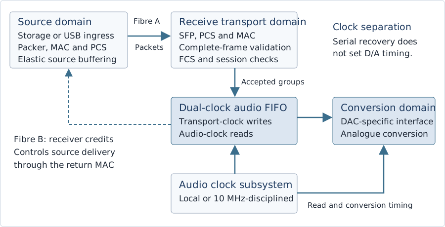
The optical receive clock supports byte recovery and FIFO writes. The audio clock supports FIFO reads and the converter interface. Feedback controls delivery from the source; it does not substitute packet arrival for the conversion reference.
6.2 Why the reference tier includes a 10 MHz input
A shared reference can make the source and sink sample-rate generators frequency coherent. This is useful when a source has a real-time acquisition or DSP clock that cannot be freely paused, when several receivers must avoid long-term differential drift, or when a system already distributes a high-quality reference. It can remove the need for a network-time servo in a dedicated installation. For that reason, an external 10 MHz input is mandatory hardware on an o2at-reference receiver and optional on o2at-basic.
The benefit is conditional on the actual audio clocks being derived from that reference with the intended rational ratios. Merely connecting two BNC sockets to the same oscillator does not prove that their audio paths are disciplined. A common reference suppresses relative frequency error in a properly locked design; it does not by itself align divider phase, sample number, stream start or DAC group delay. Different startup phases can leave a fixed offset even when long-term rates agree.
The earlier phrase “zero-ppm-drift synchronous FIFO operation” is therefore an idealised frequency result, not a complete synchronisation method. Real lock acquisition, reference faults, holdover drift and servo behaviour require measurement and status reporting. Multiple DACs needing sample-accurate acoustic alignment require an explicit epoch or trigger mechanism and calibration beyond v0.2’s consumer link profile. PTP or another time-distribution mechanism remains appropriate where network-wide time is actually required.
Frequency accuracy and short-term phase noise are also different specifications. A highly accurate 10 MHz source can produce a worse audio clock after an unsuitable synthesiser than a good local oscillator. The reference design should compare phase-noise spectra and integrated jitter over stated offset bands in internal and external modes, with repeatable conditions. A narrow reference-tracking loop and a suitable local oscillator may preserve short-term noise performance while following the long-term reference.
6.3 Clock-input and synthesiser engineering
The proposed reference input is a labelled 50 Ω BNC port. Its baseline qualification shall include a 10 MHz sine input at 0.5 V rms into 50 Ω, approximately +7 dBm, and an AC-coupled 50% square input of 2 V peak-to-peak at the termination. The square-wave qualification is zero-mean at the terminated input, with no DC offset applied. The manufacturer shall state accepted amplitude ranges, input coupling, absolute limits and lock thresholds. A 50 Ω port must not silently be specified as 75 Ω, and voltage, power and waveform conventions must be explicit.
The front end should use appropriate termination, filtering, protection and a low-additive-noise conditioning stage. It shall detect missing or out-of-range reference input. Entering or leaving external lock shall trigger a controlled transition: report status, stop or drain the stream where necessary, mute safely, reacquire and restart. Switching an audio clock source while the converter is live is not an acceptable substitute for a transition design.
Si5341 and LMK04828 are examples requiring different clock plans, not interchangeable generic fractional-N audio solutions. Si5341 is a flexible clock generator using fractional MultiSynth synthesis; its presence alone does not establish that it attenuates input jitter as required. LMK04828 is a dual-loop jitter-cleaner/distribution device whose oscillator, PLL and divider constraints must be checked against the desired audio rates. The usual LMK04828 dual-loop cleaning plan also requires an external VCXO or tunable crystal. Neither part should be selected from its headline jitter number without analysing the full reference-to-output transfer.21
The 44.1 and 48 kHz families shall have explicit frequency plans, including reference division, oscillator choice, output division, spur locations, lock time and output interface. At the new extreme rates, familiar 256 × Fs assumptions are often inappropriate. Use the converter’s supported clock architecture rather than multiplying a legacy ratio until it exceeds the device’s limits. FPGA PLLs can serve PCS and internal logic, while the conversion clock should be provided by a measured clock subsystem appropriate to the DAC.
A shared coaxial clock distributor may reconnect chassis electrically through BNC shields even when the audio path is optical. Therefore, O2AT guarantees a non-conductive audio-link path, not unconditional whole-system galvanic isolation. A reference installation must account for those parallel paths and any isolation implemented by the clock inputs or distribution equipment.
6.4 Three rate-control cases
This table is wider than the reading column. Scroll horizontally to read all columns.
| Case | Who controls sample production? | Required behaviour |
|---|---|---|
| Stored or generated playback with elastic source | Receiver clock sets consumption; source can fetch or generate on demand | Use receiver credits and bounded source buffering. The source shall stop advancing into the link when grant is exhausted. |
| Actual source and DAC clocks share a coherent reference | Both sample clocks follow the same valid frequency plan | Obey cumulative credits at all times; verify long-term occupancy. Shared frequency does not define sample epoch or authorise a burst beyond its grant. |
| Independent fixed-rate live source | Source clock cannot pause and is not locked to the DAC | A finite FIFO eventually fails under sustained mismatch. Lock a real clock, use explicit rate conversion, or reject the transparent mode. |
A legacy S/P-DIF or ADAT input is an important fixed-rate example: its stream continues according to the sending device’s clock and has no o2at credit interface. An active bridge must establish a common clock, control the true source where possible, or use an explicitly selected rate-conversion path. A future source-clock-tracking profile would need its own estimator, servo and jitter-transfer specification. Neither buffering nor PAUSE alone makes an arbitrary unlocked legacy source transparently synchronous with a local DAC.
IEEE 802.3x PAUSE is a supplementary direct-link safety mechanism. It asks the adjacent transmitting MAC to suspend data transmission, using a 16-bit pause-time value in units of 512 bit times. It is not an audio-rate feedback message and is not forwarded as an end-to-end command by ordinary bridges. On a switched path it controls the neighbouring switch port, not the original audio producer. It can also block unrelated traffic on that link.22
PAUSE may help an elastic, unlocked source avoid a transient receive overflow, provided it responds in time and has upstream storage. It cannot repair indefinite drift from a free-running live source, make an isochronous USB stream retransmittable or prevent a receiving FIFO from draining while a source is paused. The normative o2at receiver-credit mechanism therefore remains necessary; a USB bridge must propagate demand to the USB audio feedback mechanism as well.
6.5 Buffer sizing, latency and loss behaviour
Buffer sizes shall be expressed in bytes and audio groups with an associated format, not simply in “samples”. At stereo PCM32/3,072 kHz, 16,384 sample groups occupy 131,072 bytes and represent 5.333 ms. Eight channels require 524,288 bytes for the same group count. For DSD, a group spans 32 one-bit times per channel, so the group rate is the DSD bit rate divided by 32.
For an uncompensated relative rate error ε, the approximate time to consume an available FIFO margin of M groups is M / (group_rate × |ε|). As an illustration, a 1 ms margin with 50 ppm mismatch lasts about 20 s. A large FIFO postpones a steady-state problem; it does not eliminate it. Margin must also cover in-flight packets, source response time, processing stalls and any admitted switch bursts.
An initial reference design may target 0.5–2 ms of FIFO occupancy, but this is a prototype operating range, not a universal latency promise. Define the packetisation deadline, the largest allowed burst, the credit update interval and the worst-case control round trip, then size free space above the high watermark accordingly. Credits shall count data already sent but not yet consumed so that outstanding packets cannot overrun the receiver.
The latency budget includes packet assembly, serialisation, fibre propagation, switch forwarding/queueing if present, FIFO residence and the converter interface. A full 1,440-byte audio packet occupies 11.952 µs of tagged 1G wire time including IFG. That is only one component of the path. At low rates, a 125 µs packetisation deadline avoids waiting 3.75 ms to fill a stereo 48 kHz packet. Shorter packets trade bandwidth efficiency for assembly latency.
Ethernet FCS detects frame corruption; it is not forward error correction and there is no mandatory retransmission of late audio. Frames failing FCS or syntax validation are discarded and counted. A confirmed gap, invalid active-stream state or underrun shall invoke that stream’s defined mute/restart procedure; unrelated malformed or foreign traffic shall not mute an admitted stream. PCM may be ramped towards zero by an explicitly identified output-protection stage. Raw DSD shall not be replaced blindly by an all-zero bitstream, which represents a large DC condition in the one-bit domain. Use converter mute or a validated DSD idle/transition sequence.
6.6 Exact clock ratios and acceptance measurements
For a nominal 10,000,000 Hz reference, the following ratios are exact arithmetic frequency targets. They are not validated register configurations for any particular synthesiser. In both families, a 32-bit DSD group advances at the corresponding maximum PCM sample-group rate.
This table is wider than the reading column. Scroll horizontally to read all columns.
| Clock target | Frequency, Hz | Exact ratio to 10 MHz |
|---|---|---|
| PCM sample rate, 44.1 family | 2,822,400 | 882 / 3,125 |
| PCM sample rate, 48 family | 3,072,000 | 192 / 625 |
| DSD2048 bit clock, 44.1 family | 90,316,800 | 28,224 / 3,125 |
| DSD2048 bit clock, 48 extension | 98,304,000 | 6,144 / 625 |
A published clock plan shall identify reference frequency, programmed ratios, oscillator and divider ranges, output electrical interface, acquisition time and fault policy. Exact rational arithmetic removes nominal ratio error. It does not remove reference frequency error, residual loop noise, fractional spurs or startup phase ambiguity. Common frequency discipline is therefore assessed separately from a shared sample epoch.
Clock acceptance shall report output frequency and uncertainty, relative drift between source and sink, phase-noise spectra with stated integration limits, discrete spurs, and time-domain period or phase error. Test both rate families, internal and external reference modes, optical idle and maximum admitted traffic, temperature variation, reference interruption and reacquisition. Absolute frequency accuracy requires an independent measurement reference; comparing two clocks disciplined by the same source only establishes their relative behaviour.
Log FIFO occupancy and cumulative group counts during the same tests. Common-reference operation shall demonstrate bounded occupancy without sample insertion or deletion. Receiver-paced operation shall demonstrate stable upstream rate control across the admitted delay and oscillator-error envelope. Declare holdover duration and drift bounds; a fixed-rate transparent stream shall stop safely before its remaining FIFO margin can be exhausted. A synthesiser lock indication does not replace these measurements.
7. Technical Challenges & Reference Implementation
7.1 Power, RF coupling and clock-domain crossings
Place the optical cage and high-speed PHY circuitry away from the lowest-noise oscillator, DAC reference and analogue output paths. Use a controlled return-current structure, appropriate cage bonding, local regulation and filtering, adequate thermal paths and a layout validated for the actual serial channel. Galvanic isolation between boxes does not isolate a DAC’s local analogue circuitry from its own SFP supply current.
Select optics by supported rate, optical budget, qualification, diagnostics and measured electrical behaviour. A non-retimed low-power module can be a sensible reference choice, but CDR absence is not a universal conformance requirement. Faster optics do not necessarily corrupt conversion timing, and a nominally slower optic is not automatically quieter. Test supply spectra and analogue output under realistic payload, burst, idle, module temperature and cable-loss conditions.
A dual-clock FIFO should use independently clocked read and write pointers, Gray-coded pointer transfer, synchronisers with a documented metastability analysis, and correctly constrained reset release. Do not synchronise a changing binary multi-bit counter by placing two flip-flops on each bit. Data storage, metadata and format changes must cross as a coherent transaction. Vendor FIFO IP can help, but its configuration and timing constraints still require review.
The receive path shall not release an audio packet to the playback FIFO until the complete frame has passed FCS and syntax checks. Either buffer the whole frame before committing it or support an atomic rollback that never exposes corrupt groups. A late CRC result cannot undo samples already converted. Likewise, a format change shall drain or discard the old stream under mute before a new session is admitted.
7.2 FPGA and host reference design
A practical first platform is Sipeed’s Tang Mega 138K Pro, which provides two SFP+ cages and a GW5AST-LV138FPG676A device with transceivers spanning rates that include 1.25 Gb/s. The baseline experiment uses a qualified 1G optic in a compatible cage and configures the FPGA accordingly. It does not require operating the optical link at 10G merely because the board has SFP+ cages.23
The project must implement or integrate the 1000BASE-X PCS/PMA, MAC, receive validation, control-state machine, audio packing, dual-clock FIFOs and output interface. Verify the available transceiver reference clocks and rate configurations before board commitment. The board’s commercial Gowin toolchain requirement and silicon-revision restrictions must be recorded. Open RTL does not imply a fully open implementation toolchain or a ready-made, validated O2AT bitstream.
A host prototype can send raw Ethernet frames through a suitable NIC, but an AF_PACKET socket does not automatically provide zero-copy, bounded scheduling latency or reliable PHY control. Measure the actual path, use appropriate batching or ring buffers where supported, and keep audio buffering and receiver credits visible. The release should publish a packet dissector, a reference encoder/decoder, deterministic test vectors and reproducible builds before attempting broad hardware optimisation.
The optional expansion profile uses 10GBASE-R at 10.3125 GBd and a 10.000 Gb/s MAC service. Qualified 10GBASE-SR or LR media are allowed under an explicit profile. A mixed-speed switch can bridge a 10G source to a 1G DAC port only after admission to the slower egress. Mixed-speed paths shall also bound source or upstream-switch bursts to the qualified egress service and queue capacity. Average admission and receiver credits alone do not protect an intermediate switch from a rapid burst at 10G. The protocol remains raw Layer 2; no IP workload is required to justify a 10G link.
7.3 USB ingress and DAC egress impose separate ceilings
The conventional high-speed USB 2.0 high-bandwidth isochronous endpoint limit is three transactions of up to 1,024 bytes per 125 µs microframe. The maximum payload is therefore 24.576 MB/s, or 196.608 Mb/s. Stereo PCM32/3,072 kHz requires exactly that nominal payload, leaving no positive rate margin for asynchronous clock error. A 385-sample-group microframe would need 3,080 bytes. The 44.1 kHz-family extreme fits the theoretical three-transaction budget, but endpoint and driver support remain separate requirements.24
A USB-to-o2at bridge also needs a real feedback controller. Ethernet credits prevent receive-buffer overrun, but do not by themselves specify UAC2 feedback. Estimate downstream consumption from cumulative DAC-side group counters against the bridge’s observed USB microframe count, filter bounded report-delay variation and control source-buffer occupancy. Define the conversion from o2at groups to the advertised USB sample units; PCM and vendor-specific native-DSD endpoints need different mappings. Verify loop stability, startup, positive/negative clock offsets and feedback quantisation. Packet interarrival variation shall not become the DAC conversion-clock reference.
Generic “XMOS UAC2” is not enough evidence for these rates. As a concrete documented implementation limit, XMOS lib_xud v4.0.1 supports at most two transactions per microframe, on the specified xcore.ai configuration. That yields 16.384 MB/s and falls short of stereo DSD2048 or PCM32 at 2,822.4/3,072 kHz. This is a limit of the cited implementation, not a statement about every possible future XMOS design.25
Begin extreme-rate transport validation with a native FPGA pattern generator or a separately qualified high-throughput ingress. A suitable USB 3 implementation is a possible later bridge. The intended user-facing format must be supported by the source software, host driver, endpoint descriptors, device firmware and downstream interface. A successful optical packet test is not evidence that a present-day music server can generate the same format.
At the DAC side, two 32-bit I²S slots require BCLK = 64 × Fs. PCM32/2,822.4 kHz therefore needs 180.6336 MHz BCLK, and PCM32/3,072 kHz needs 196.608 MHz. One serial DSD line per channel needs 90.3168 or 98.304 MHz at the extreme rates. These are calculations from the stated packing, not guaranteed operating modes of existing I²S-over-HDMI links. Multiple internal lanes or a converter-specific interface may be necessary.26
7.4 Applying the architecture to the N30SA, µDDC and Harmony
Aurender explicitly states that an external clock input on its source does not discipline asynchronous USB audio; the downstream audio device controls average data flow. Thus, connecting an N30SA by USB to a µDDC does not make the µDDC the N30SA’s USB signalling-clock generator. In asynchronous USB operation, the sink’s feedback controls the host’s average delivery of audio samples. The µDDC’s internal relationship between that feedback and its external reference remains undocumented in the public specifications reviewed here. The N30SA’s reference-clock treatment of AES/S/P-DIF is a different path.27
LAiV specifies a 10 MHz, 50 Ω clock input for the Harmony µDDC, accepting square or sine waves, and lists PCM through 768 kHz and DSD512 on its USB/I²S paths. Those specifications do not establish support for DSD2048 or PCM3072, nor do they disclose every internal feedback and conversion-clock relationship. The original Harmony DAC in this experiment has no 10 MHz input, so reference discipline would be applied at the intermediate interface rather than directly at that DAC.28
The useful first experiment is therefore a transparent bridge within the existing equipment’s supported formats: asynchronous USB ingress, o2at optical transport, a receiver with explicit local or disciplined read clock, and a validated µDDC/DAC-compatible output. Confirm where the downstream conversion clock is actually selected. Separate transport stress tests at DSD2048/PCM3072 can then demonstrate future capacity without implying that the current playback chain accepts those rates.
8. Device Labelling, Diagnostics & User Experience
An O2AT socket should be as clear to use as the TOSLINK socket it replaces. The label should identify an audio interface and its optical class. It should not imply that any similarly shaped SFP port on a switch, USB extender or proprietary DAC is interchangeable. A direct connection should expose only useful outcomes: link established, compatible format, reference state and any fault requiring attention.
This table is wider than the reading column. Scroll horizontally to read all columns.
| Marking or diagnostic | Required interpretation |
|---|---|
| o2at 1G / SX / LC duplex | Standard baseline optical profile; matched 850 nm multimode optics and fibre |
| o2at-reference / 10 MHz / 50 Ω | External clock input present, with the electrical acceptance limits in the manual |
| PCM32 maximum rate; DSD rate and family | Report verified endpoint capabilities, including the 44.1 or 48 kHz DSD family |
| Link / session / clock state | Separate physical link-up, negotiated session and conversion-clock lock; one green light must not hide an unsupported format |
| Counters | FCS rejection, sequence gaps, syntax errors, FIFO extrema, underrun/overrun, reference loss and restart count |
| Measured latency mode | Report the configured packetisation deadline and FIFO target, plus the qualified topology, rather than a generic “zero jitter” claim |
After discovery, the source shall present only mutually supported modes and refuse an over-budget channel/rate combination. Reference loss should produce a clear status with a documented holdover or controlled stop policy. A user should not need to choose endian order, DSD bit direction or an HDMI pin map. Those choices belong to the standard and the endpoint implementation.
Diagnostic access may be local, through a companion control application or via an optional management interface. It shall not be necessary for basic direct playback. Optical O2AT does not carry electrical power between devices. Any separate powering arrangement is outside the optical audio profile and must not be advertised as inherent optical PoE.
9. Industry Adoption, Validation & Governance
9.1 Why adoption will be gradual
Manufacturers already have substantial investment in USB receivers, XMOS firmware, S/P-DIF input circuits, certification, drivers and support processes. Those are working product assets. A new optical socket adds a cage, an Ethernet-capable digital path, firmware, power and thermal requirements, plus another interoperability matrix. Conservative adoption is a rational response to those costs, especially while compatible sources are scarce.
Consumers recognise TOSLINK and USB and can connect them with inexpensive cables. O2AT must therefore win on clear practical benefits: isolation, a documented format envelope, robust negotiation, replaceable standard optics and dependable operation. Extreme sample rates provide design headroom, but do not by themselves establish a listening benefit or persuade a manufacturer to redesign a successful DAC.
Boutique partnerships can create the first compatible source module, receiver board and reference DAC input. A small common baseline is more useful than several incompatible demonstrations. Open reference RTL, schematics, conformance traces and an accessible analyser give independent engineers a way to reproduce behaviour and identify defects without relying on brand-specific claims.
9.2 A measurable validation programme
- Protocol: publish exact PCM and DSD test vectors; validate packing, channel maps, sequence wrap, session restart, malformed lengths, unknown critical TLVs and experimental EtherType coexistence.
- Link and thermal: test qualified optics over the declared loss and temperature range, including module replacement, loss of signal, fault recovery, rail transients and sustained maximum-rate traffic.
- Rate and buffering: run both frequency families, stereo and eight-channel extremes, bursty hosts, bounded switch contention, controlled ppm offsets and clock-source changes. Log long-term FIFO occupancy and grants.
- Clock and analogue: measure phase-noise spectra and integrated jitter with stated bandwidths; compare converter output under internal/external reference, link idle/full traffic and alternative qualified modules.
- Interoperability: demonstrate two independent source implementations and two independent receivers, plus a documented switch configuration for the optional fabric profile.
- Failure behaviour: inject missing, duplicated, stale, out-of-order and corrupted frames; verify counters, bounded reaction, safe mute and recovery without unintended full-scale PCM or DSD output.
For an illustrative error-rate check, zero observed errors over N independent tested bits gives an approximate one-sided 95% upper bound of 3/N on the bit-error probability. A 24-hour test at 1.25 Gbit/s exercises about 1.08 × 10¹⁴ serial bits, giving an illustrative bound near 2.8 × 10⁻¹⁴ under that model. A MAC-only payload test measures a different population and should be labelled accordingly. Neither result proves zero future errors or audible superiority.
Likewise, a hypothetical BER of 10⁻¹² at 1 Gbit/s corresponds to a mean raw-bit error interval of about 1,000 s, not eleven days. Packet error statistics, detected/rejected frames and actual audio interruption rates are distinct quantities. Publish exposure time, tested bit population, confidence model and failure policy rather than a single reassuring number.
9.3 Release gates and future extensions
Version 0.2 should remain an engineering draft until the packet/control definitions have two independent implementations, the baseline optical profile has qualified parts and the conformance suite exposes no unresolved safety-of-output failures. Public commercial deployment also requires a proper protocol identifier. A governance group should manage the capability registry, change process, errata and reference releases with public decisions.
Future work may add sample-accurate multi-DAC epochs, redundant paths, authenticated control, scheduled Ethernet operation and broader sample formats. These should use negotiated extensions and explicit version changes where necessary. The mandatory consumer baseline should remain small enough to implement without a full IP stack, PTP servo or proprietary licence. The standard’s success should be measured by interchangeable endpoints and reliable playback, not by its longest list of optional features.
9.4 Engineering review status and evidence required
This revision has been checked for format arithmetic, protocol consistency, clock-domain assumptions and alignment with cited primary documentation. It is an engineering proposal suitable for external technical review, not a completed independent peer review or a measured prototype report. The distinction matters most for conversion-clock performance and deterministic latency, which cannot be certified from the packet format alone.
This table is wider than the reading column. Scroll horizontally to read all columns.
| Review item | Status in v0.2 | Required evidence before a conformance claim |
|---|---|---|
| 1G SFP capacity through DSD2048 / PCM3072 | Analytically established for the stated packetisation and channel counts | Bit-exact sustained tests, measured packet loss and admitted burst behaviour |
| Wire format and control semantics | Explicit draft definitions with resolved length, session, credit and final-packet rules | Independent implementations, published vectors and fault-injection results |
| 10 MHz to audio clock plan | Frequency relationships and measurement requirements defined; no universal component solution asserted | Device-specific synthesis/divider plan, lock/holdover traces, spur and phase-noise measurements |
| Isolation and endpoint noise | Optical path is non-conductive; other installation paths remain relevant | Complete grounding review, rail/noise measurements and DAC-output comparison |
| Latency and clock feedback | Budget components and control requirements identified | Worst-case measurements for the admitted topology and a stable USB/receiver feedback loop |
| Legacy TOSLINK and future ADAT migration | PCM/DSD transport available; broader legacy profiles explicitly scoped | Metadata mapping, format negotiation and clock-authority tests on real legacy equipment |
Appendix A. Commercial Pushback from the Audiophile Cable Industry
A commodity optical interface challenges the economics of premium metallic digital interconnects. The original proposition compared USB, AES/EBU, S/P-DIF and silver I²S-HDMI cables priced at US$500 to US$5,000 or more with an US$8 duplex-LC patch cord and US$15 SFP modules. In this revision those figures are illustrative commercial assumptions, not verified current offers or a guaranteed system bill of materials. Two endpoints, their optics, electronics, integration and compliance work must all be counted.
A.1 What commodity fibre changes physically
A non-conductive glass-fibre signal path cannot carry a chassis-to-chassis ground current along the fibre. A continuous metallic conductor can. Silver purity, conductor geometry and shielding do not turn that conductor into glass. However, transformer-coupled electrical interfaces and active isolation products can provide galvanic barriers of their own, and ordinary TOSLINK already provides optical isolation. The defensible comparison is the complete interface topology, not a claim that every expensive cable is equivalent or every copper-based system lacks isolation.
A correctly specified inexpensive optical patch cord can therefore deliver the relevant isolation property without precious-metal conductors. Its quality still matters for insertion loss, connector polish, mechanical durability, bend handling and reliable mating. O2AT does not eliminate engineering quality; it relocates much of the relevant performance from luxury conductor construction to standard optical specifications and endpoint design.
A.2 Likely incentives, not an allegation of coordinated resistance
Some firms whose margins depend on premium metallic digital cables may have little incentive to promote an interchangeable optical connection. Others may sell qualified fibre assemblies, rugged connectors, installation services, optical diagnostics or complete interface products. These are plausible commercial responses, not evidence of a coordinated campaign by any manufacturer. No particular firm’s motives can be established from its product price.
The strongest adoption argument is an open and measurable interface. Demonstrate bit integrity, controlled failure behaviour, real isolation boundaries, reproducible clock measurements and an honest complete cost. Listening comparisons can supplement that evidence when appropriately controlled, but they cannot substitute for the transport specification or prove that an expensive digital cable is necessary for a correctly functioning link.
Engineering claims and their limits
This table is wider than the reading column. Scroll horizontally to read all columns.
| Claim | Engineering response |
|---|---|
| A better optical cable must change the decoded sample values | Within the operating margin, correctly received values are the transmitted values. Diagnose loss and detected errors rather than attributing a new numerical resolution to the cable. |
| Optical isolation guarantees no noise anywhere in the DAC | It removes the conductive signal path between boxes. The receiver’s own optics, power system and digital logic still generate local activity. |
| An external clock always improves conversion | Compare the complete reference-to-audio-clock chain. Frequency accuracy, phase noise, spurs and clock-selection behaviour are separate measurements. |
| 1G is superior to 10G on every relevant metric | 1G is the preferred low-power consumer baseline. 10G has real advantages in aggregate capacity, higher channel counts and serialisation time. |
| A boutique cable business must resist an open optical standard | Commercial incentives vary. The standard should succeed through interoperability, test evidence and useful products, without speculation about individual firms. |
Appendix B. Glossary of Acronyms and Engineering Terms
This glossary is the terminology companion to the source bibliography. Definitions are scoped to the proposed O2AT interface and distinguish optical hardware, Ethernet transport and audio timing.
This table is wider than the reading column. Scroll horizontally to read all columns.
| Acronym or term | Meaning in this document |
|---|---|
| 1000BASE-X / SX / LX | X identifies the 1G PCS family; SX is the short-wavelength multimode optical profile and LX is a longer-wavelength optical profile. Compatible PHY, module and fibre choices are required. |
| 10GBASE-R / SR / LR | R identifies the 64b/66b 10G PCS family; SR and LR identify short- and long-reach optical profiles. They do not define an audio format. |
| 8b/10b; 64b/66b | Line codes used here by 1G and 10G Ethernet respectively. Their overhead explains why serial signalling rates exceed MAC service rates. |
| ADAT / S/MUX | ADAT Lightpipe is a multichannel optical framing system. Sample multiplexing carries higher sample rates by consuming additional channel slots; a future O2AT bridge needs an explicit clock policy. |
| AES3 / AES10 / AES67 | Professional stereo digital audio, MADI multichannel audio, and audio-over-IP interoperability standards respectively. They solve different interface problems. |
| AoIP | Audio over Internet Protocol. Media carried through an IP network, commonly with UDP and RTP in interoperable professional audio systems. |
| Asynchronous USB audio | USB audio operation in which sink consumption is independent of USB bus timing and feedback controls the host’s average delivered sample rate. |
| AVB / Milan | Audio Video Bridging is an IEEE family of timing and traffic-management mechanisms. Milan defines an interoperable professional media profile built on AVB. |
| BCLK / LRCLK / MCLK | Bit clock, left/right or word-select clock, and master clock. Their frequencies and relationships are determined by the converter interface, not simply by a connector. |
| BER | Bit-error ratio or probability under defined conditions. A measurement needs a tested bit population, exposure and confidence model. |
| BiDi | Bidirectional optical module arrangement using different wavelengths on a fibre. It is distinct from this baseline’s two-fibre duplex-SX arrangement. |
| Big-endian | A multi-byte number is represented with its most significant byte first. This describes packet content, not a redefinition of Ethernet physical bit order. |
Glossary of acronyms and terms (continued)
This table is wider than the reading column. Scroll horizontally to read all columns.
| Acronym or term | Meaning in this document |
|---|---|
| BMC | Bi-Phase Mark Coding. Self-clocking coding associated with conventional IEC 60958/AES3 streams. |
| BNC / impedance | A coaxial connector family. A stated 50 Ω or 75 Ω impedance is a property of the complete interface and termination, not a cosmetic label. |
| CDR | Clock and data recovery. Recovers serial timing for symbol decisions; it is distinct from the clock driving D/A conversion. |
| CDC | Clock-domain crossing. Transfer between unrelated or independently phased clock domains, requiring a defined metastability and data-coherency strategy. |
| Channel group | In o2at PCM, one 32-bit container per channel at a sample instant. In DSD, one 32-bit chronological block per channel. |
| Clock discipline | Control of an oscillator or synthesiser against a reference. Frequency discipline alone does not identify a shared sample epoch. |
| Clock epoch | A common definition of sample zero or another time origin. Required for aligned start across independent converters; not supplied by frequency lock alone. |
| Credit | A receiver-issued cumulative permission to transmit up to an exclusive group index. A duplicate cumulative grant must not allocate extra space. |
| DAC / DDC | Digital-to-analogue converter; digital-to-digital converter. A DDC can change interface format while leaving the downstream conversion clock architecture product-specific. |
| Deterministic latency | A latency bound established under explicit traffic, topology and implementation assumptions. It is not implied by Layer 2, an EtherType or a fast link alone. |
| DoP | DSD over PCM framing. Lossless carriage of unchanged DSD bits in PCM-shaped containers with identifying markers. |
| DSD / DSD2048 | Direct Stream Digital, a one-bit audio representation. DSD2048 normally means 44,100 × 2,048 = 90.3168 MHz per channel; the 48 kHz-derived extension is explicitly labelled. |
| DSD32 | The o2at packing of 32 chronological DSD bits in one big-endian word per channel. It is neither 32-bit PCM nor a DSD rate multiplier. |
| Duplex LC | Two LC optical connector paths, one in each direction for the baseline link. Duplex describes directionality and fibre arrangement, not Ethernet compatibility. |
Glossary of acronyms and terms (continued)
This table is wider than the reading column. Scroll horizontally to read all columns.
| Acronym or term | Meaning in this document |
|---|---|
| EMI / RF | Electromagnetic interference and radio-frequency activity. Coupling depends on physical paths, spectra, impedances and the receiving circuitry. |
| EtherType | The Ethernet field identifying the encapsulated protocol. 0x88B5 is for local experimental use, not a permanent O2AT allocation. |
| FCS / CRC | Frame check sequence and cyclic redundancy check. Ethernet uses its FCS to detect corruption; this is not audio forward error correction. |
| FEC | Forward error correction. Additional redundancy allowing some errors to be repaired. It is not provided merely by an Ethernet FCS. |
| FIFO | First-in, first-out storage. A dual-clock FIFO separates write and read domains but requires a long-term rate-control strategy. |
| FPGA / RTL | Field-programmable gate array; register-transfer-level design description. Open RTL does not automatically make the implementation tools or third-party IP open. |
| Galvanic isolation | Absence of a conductive connection across a specified barrier. A fibre signal path can be isolated while other installation connections still join chassis. |
| GBd; Gb/s; MB/s | Gigabaud, gigabits per second and megabytes per second. Decimal units are used in the capacity calculations; one byte is eight bits. |
| Gray code | A code in which adjacent count values differ by one bit. Used with suitable synchronisation and constraints for FIFO pointer crossing. |
| Holdover | Operation from a local clock model after the external reference is lost. Drift and allowed duration must be specified and monitored. |
| IEC 61937 | Encoded non-linear-PCM audio carriage over the IEC 60958 interface family. Its burst and metadata semantics require an explicit legacy-carriage profile. |
| I²S / LVDS | Inter-IC Sound serial bus; low-voltage differential signalling. An HDMI-shaped I²S connector does not define a universal external pinout. |
| IFG | Interpacket gap, also called interframe gap. The minimum idle interval consumes link time and is included in the occupied-wire calculation. |
| ISI / modal dispersion | Inter-symbol interference; spreading caused by different optical propagation paths. Link impairment depends on fibre, launch, length and receiver behaviour. |
Glossary of acronyms and terms (continued)
This table is wider than the reading column. Scroll horizontally to read all columns.
| Acronym or term | Meaning in this document |
|---|---|
| Jitter / phase noise | Timing variation and its frequency-domain description. Clock quality must be stated with conditions and a measurement bandwidth. |
| Layer 2 / Layer 3 | Ethernet link-layer forwarding versus network-layer routing. Ordinary switches bridge o2at frames; IP routers do not route the raw protocol. |
| MAC / PCS / PMA | Media access control, physical coding sublayer and physical medium attachment. These layers provide framing, coding and serial functions around the optical module. |
| MADI | Multichannel Audio Digital Interface, standardised by AES10. A dedicated professional serial audio interface. |
| MSA / SFF | Multi-Source Agreement and Small Form Factor specifications. They standardise aspects of modules and interfaces, not a complete audio protocol. |
| MSB / LSB | Most significant bit and least significant bit. Context distinguishes this numerical abbreviation from the manufacturer MSB Technology. |
| MTU | Maximum transmission unit. The baseline Ethernet payload is at most 1,500 bytes, including the 12-byte o2at header. |
| Native DSD | DSD transported without a DoP marker/container wrapper. It does not imply a universal USB implementation or automatic support by a DAC. |
| Nonce / session | A fresh association value; a negotiated immutable audio context. The proposed nonce/session fields prevent routine stale-context confusion, not deliberate forgery. |
| NRZ | Non-return-to-zero signalling. A component’s NRZ rate rating must be related to the actual pulse-width requirements of the intended encoded stream. |
| o2at | The lowercase identifier for Open Optical Audio Transport in protocol magic, code and schemas. O2AT is the document’s display name. |
| OM3 / OM4 / OS2 | Optical-fibre categories. OM3/OM4 are multimode choices for the proposed SX baseline; OS2 is used with appropriate single-mode optics. |
| PAUSE | IEEE 802.3x link-local MAC flow control. It is not a forwarded audio feedback message or a solution to unlimited fixed-clock drift. |
| PCM32 | Pulse-code modulation carried in a 32-bit signed container. The negotiated number of valid bits may be 16, 24 or 32. |
Glossary of acronyms and terms (continued)
This table is wider than the reading column. Scroll horizontally to read all columns.
| Acronym or term | Meaning in this document |
|---|---|
| PCP / QoS / VLAN | Priority code point, quality of service and virtual LAN. Their effective treatment depends on switch configuration and admission policy. |
| PDV | Packet-delay variation. Changes arrival timing and FIFO occupancy; it need not set the DAC’s sample timing. |
| PLL / fractional synthesis | Phase-locked loop and generation of rationally related frequencies. Device architecture, division ratios, spurs and loop bandwidth determine actual performance. |
| PMMA / POF | Polymethyl methacrylate and plastic optical fibre, commonly used in consumer optical audio cables. |
| ppm | Parts per million, a relative frequency measure. One ppm means a ratio error of 10⁻⁶, not a phase-noise specification. |
| Pro ISL / Pro USB | MSB’s proprietary optical interface and its USB-to-optical adapter. These are not o2at or ordinary Ethernet transports. |
| PTP / gPTP | Precision Time Protocol and its IEEE 802.1AS-related network-time profile. Frequency, phase and time synchronisation requirements must be distinguished. |
| Q32.32 | An unsigned 64-bit fixed-point representation with 32 integer and 32 fractional bits, used by the optional group-rate pacing hint. |
| SerDes | Serialiser/deserialiser. A qualified high-speed receive path includes the relevant recovery and alignment functions, not simply ordinary differential GPIO. |
| SFP / SFP+ | Pluggable optical-module form-factor families. Compatible mechanics do not establish the module’s line rate, wavelength or carried protocol. |
| TLV | Type-length-value record. The o2at control format uses eight-byte record alignment and explicit critical-extension semantics. |
| TOSLINK | Toshiba-origin consumer optical interface family. This paper distinguishes its installed capabilities from the scope of all IEC 60958 extensions. |
| UAC2 | USB Audio Class 2.0. Class support alone does not prove native DSD handling, high-bandwidth endpoint implementation or the highest proposed o2at rates. |
| VCO / VCXO | Voltage-controlled oscillator and voltage-controlled crystal oscillator. Clock-loop choices influence reference tracking and local phase-noise performance. |
| Wire utilisation | The fraction of link time occupied by a stream, including framing, preamble and gap. It is larger than the raw audio payload rate. |
Bibliography and primary references
References were checked on 19 November 2026. Standards and manufacturer documentation establish factual boundaries; bandwidth, latency and buffer figures identified as calculations are derived in this paper. Public product information does not disclose proprietary wire formats. An edition cited here is a design reference, not a claim of certification.
R01. IEC. IEC 60958-1:2021, Digital audio interface, Part 1: General. Public scope and publication record.
https://webstore.iec.ch/en/publication/62829
R02. IEC. IEC 60958-5:2021, Digital audio interface, Part 5: Consumer application enhancement.
https://webstore.iec.ch/en/publication/59808
R03. Toshiba Electronic Devices & Storage Corporation. TOTX1950A(F), fibre optic transmitting module, Rev. 3.0, 15 April 2026, pp. 1–3.
https://toshiba.semicon-storage.com/info/docget.jsp?did=37194&prodName=TOTX1950A(F)
R04. Toray. RAYTELA plastic optical fibre, material and optical product specifications.
https://www.electronics.toray/en/products/raytela/
R05. Cliff Electronic Components. TOSLINK optical connectors, JIS F05, JEITA and CP-1201 compatibility descriptions.
https://www.cliffusa.com/products/optical/toslink.htm
R06. DoP project. DoP Open Standard, Version 1.1, Method for transferring DSD Audio over PCM Frames, §§2–3.
https://dsd-guide.com/sites/default/files/white-papers/DoP_openStandard_1v1.pdf
R07. NXP Semiconductors. UM11732, I²S bus specification, Rev. 3.0, 17 February 2022.
https://www.nxp.com/docs/en/user-manual/UM11732.pdf
R08. Audio Engineering Society. AES10, Serial multichannel audio digital interface (MADI), standards catalogue and scope.
https://aes.org/publications/standards-store/?id=17
R09. Audio Engineering Society. AES67-2023, High-performance streaming audio-over-IP interoperability.
https://aes.org/publications/standards-store/?id=140
R10. Audinate. What are the benefits of AES67? Dante transport and RTP-over-IP interoperability explanation.
https://support.getdante.com/hc/en-gb/articles/5508266895391-What-are-the-benefits-of-AES67
R11. Avnu Alliance. Milan Specification, consolidated AVB interoperability specification and supporting IEEE standards.
https://avnu.org/resource/milan-specification/
R12. HiFi Rose. RS130–RD160 SFP Connection Guide, manufacturer-authored connection instructions.
https://cdn.shopify.com/s/files/1/0631/7608/1655/files/SFP_Connection_Guide_EN_68.pdf?v=1736876712
R13. HiFi Rose. RS130, RD160 and RSA720 owner manuals, manufacturer downloads. Optical USB and Ethernet interfaces are documented separately.
R14. MSB Technology. About MSB fibre connections, Pro ISL optical media, compatibility and non-Ethernet warning.
https://msbtechnology.com/support/about-msb-fiber-connections/
R15. MSB Technology. Digital inputs, Pro ISL clock return and error-handling description.
https://msbtechnology.com/dacs/digital-inputs/
R16. MSB Technology. Pro USB adapter, USB conversion, clocking and format specifications.
https://msbtechnology.com/dacs/prousb/
R17. Aurender. N50 Quick Start Guide, optional MSB Pro ISL output and format capabilities.
https://ask.aurender.com/hc/en-us/articles/35347051953047-N50-Quick-Start-Guide
R18. Coherent. FTLF8519P3xyL SFP transceiver data sheet, 1000BASE-SX and power below 500 mW.
R19. Cisco. 10GBASE SFP+ Modules Data Sheet, updated 6 October 2026, Table 8.
R20. SNIA SFF Committee. SFF-8472, Management Interface for SFP+, Rev. 12.5a, 16 January 2026, internal retimer/CDR indication.
https://members.snia.org/document/dl/25916
R21. SFF Committee. SFF-8431, Rev. 4.1 with addendum, archived SFP+ electrical interface specification, §§1 and 3. Successors include SFF-8418 and SFF-8419.
https://members.snia.org/document/dl/25891
R22. Xilinx. High-Speed Serial I/O Made Simple, running disparity and 8b/10b coding explanation.
https://download.amd.com/docnav/documents/aem/books-serialio.pdf
R23. IETF. RFC 9542, IANA Considerations and IETF Protocol and Documentation Usage for IEEE 802 Parameters, April 2024. Local experimental EtherTypes.
https://www.rfc-editor.org/rfc/rfc9542.html
R24. IEEE 802.3 Ethernet Working Group. Standards and public working-group materials; MAC, 1000BASE-X and 10GBASE-R are the normative layer foundations.
R25. Skyworks. Si5341/40 Rev. D data sheet, low-jitter clock generators with MultiSynth fractional synthesis.
R26. Texas Instruments. LMK04828 data sheet, dual-loop jitter cleaner and clock distribution device.
https://www.ti.com/lit/ds/symlink/lmk04828.pdf
R27. Microsoft. How to transfer data to USB isochronous endpoints, USB high-speed transfer intervals and payload limits.
R28. XMOS. lib_xud: USB device library, XM-012026-UG v4.0.1, 8 December 2025, §10 and build options.
https://www.xmos.com/documentation/XM-012026-UG/pdf/lib_xud_v4.0.1.pdf
R29. Aurender. MC20 Quick Start Guide, §§7.2–7.3, external reference clocks and asynchronous USB.
https://ask.aurender.com/hc/en-us/articles/25352309294871-MC20-Quick-Start-Guide
R30. LAiV. Harmony µDDC technical specifications, clock input and audio input/output formats.
https://www.laiv.audio/harmony-uddc-specs
R31. Sipeed. Tang Mega 138K Pro Dock documentation, FPGA, SFP+ cages, transceiver rates and toolchain.
https://en.wiki.sipeed.com/hardware/en/tang/tang-mega-138k/mega-138k-pro.html
R32. Gowin Semiconductor. Arora V FPGA product documentation, GW5AST SerDes capabilities.
https://www.gowinsemi.com/en/product/arora-v-fpga/
R33. Seaman, M. Protocol identification in 802 LANs, IEEE 802.1 Maintenance contribution, draft 10 April 2020, §1.3.1. Experimental EtherType deployment scope.
https://ieee802.org/1/files/public/docs2020/maint-seaman-protocol-identification-0420-v00.pdf
R34. AMD. Tri-Mode Ethernet MAC Product Guide PG051, v9.0, Pause Control Frames, 11 December 2024.
https://docs.amd.com/r/en-US/pg051-tri-mode-eth-mac/Pause-Control-Frames
R35. Merging Technologies. Introduction to RAVENNA Technology, official technical overview of IP media transport and clocking.
R36. RME. Digiface USB, optical ADAT/S/P-DIF capabilities and S/MUX channel counts.
https://rme-audio.de/digiface-usb.html
R37. IEC. IEC 61937-1:2021, Digital audio: interface for non-linear PCM encoded audio bitstreams applying IEC 60958, Part 1: General, including March 2024 corrigendum.
https://webstore.iec.ch/en/publication/62828
Tunji Durodola (LinuxProphet) | pocketOne OÜ | tunji@pocketone.eu
Footnotes
- 1
R01. IEC 60958-1:2021, general interface scope; R05. Cliff TOSLINK connector specifications. Full publication details and links are listed in the bibliography.
- 2
R03. Toshiba TOTX1950A(F) data sheet; R04. Toray RAYTELA plastic optical fibre. Full publication details and links are listed in the bibliography.
- 3
R03. Toshiba TOTX1950A(F) data sheet. Full publication details and links are listed in the bibliography.
- 4
R01. IEC 60958-1:2021, general interface scope; R02. IEC 60958-5:2021, consumer extensions. Full publication details and links are listed in the bibliography.
- 5
R06. DoP Open Standard v1.1. Full publication details and links are listed in the bibliography.
- 6
R07. NXP UM11732, I²S specification. Full publication details and links are listed in the bibliography.
- 7
R08. AES10, MADI interface scope; R09. AES67-2023, interoperability scope; R10. Audinate, Dante and AES67; R35. Merging, RAVENNA technical overview. Full publication details and links are listed in the bibliography.
- 8
R11. Avnu, Milan Specification. Full publication details and links are listed in the bibliography.
- 9
R12. HiFi Rose RS130–RD160 connection guide; R13. HiFi Rose product manuals. Full publication details and links are listed in the bibliography.
- 10
R17. Aurender N50 Quick Start Guide. Full publication details and links are listed in the bibliography.
- 11
R14. MSB fibre connections guide. Full publication details and links are listed in the bibliography.
- 12
R15. MSB Pro ISL digital input description; R16. MSB Pro USB specifications. Full publication details and links are listed in the bibliography.
- 13
R05. Cliff TOSLINK connector specifications. Full publication details and links are listed in the bibliography.
- 14
R06. DoP Open Standard v1.1; R37. IEC 61937-1:2021, encoded audio carriage. Full publication details and links are listed in the bibliography.
- 15
R36. RME Digiface USB, ADAT and S/MUX specifications. Full publication details and links are listed in the bibliography.
- 16
R24. IEEE 802.3 Ethernet standards. Full publication details and links are listed in the bibliography.
- 17
R18. Coherent FTLF8519P3xyL data sheet. Full publication details and links are listed in the bibliography.
- 18
R18. Coherent FTLF8519P3xyL data sheet; R19. Cisco SFP+ data sheet, power specifications; R20. SFF-8472, optional internal retimer/CDR; R21. SFF-8431, host channels and interfaces. Full publication details and links are listed in the bibliography.
- 19
R22. Xilinx, 8b/10b running disparity. Full publication details and links are listed in the bibliography.
- 20
R23. RFC 9542, local experimental EtherTypes; R33. IEEE 802.1 contribution, experimental identification. Full publication details and links are listed in the bibliography.
- 21
R25. Skyworks Si5341/40 Rev. D data sheet; R26. TI LMK04828 data sheet. Full publication details and links are listed in the bibliography.
- 22
R34. AMD PG051, PAUSE control frames. Full publication details and links are listed in the bibliography.
- 23
R31. Sipeed Tang Mega 138K Pro documentation; R32. Gowin Arora V transceiver documentation. Full publication details and links are listed in the bibliography.
- 24
R27. Microsoft, USB isochronous endpoint limits. Full publication details and links are listed in the bibliography.
- 25
R28. XMOS lib_xud v4.0.1, high-bandwidth limits. Full publication details and links are listed in the bibliography.
- 26
R07. NXP UM11732, I²S specification. Full publication details and links are listed in the bibliography.
- 27
R29. Aurender MC20 guide, USB and clock input. Full publication details and links are listed in the bibliography.
- 28
R30. LAiV Harmony µDDC technical specifications. Full publication details and links are listed in the bibliography.